


2. DESIGN
2
−
9
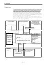
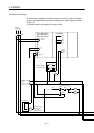
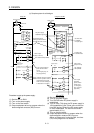
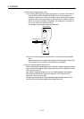
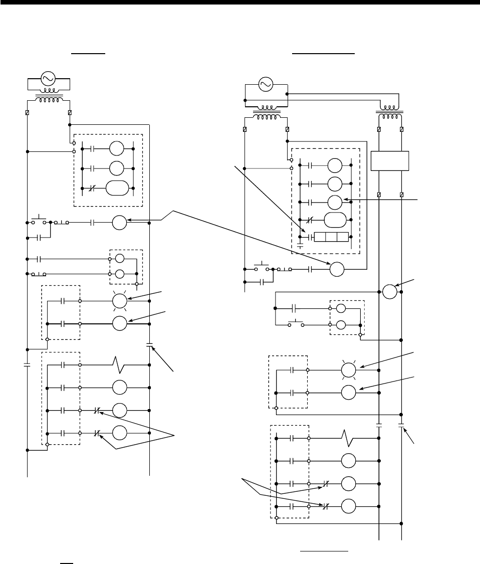
(c) Sample system circuit designs
Power supply
Power supply
Transformer
Transformer Transformer
Fuse
Fuse FuseCPU
CPU
Ym
Yn
M9084
M9006
M9039
XM
RA1
MC
Ym
Yn
M9084
TM
M9006
M9039
XM
TM
TM
RA1
MC1 NO M10
Program
DC power
supply
(+)(-)
Fuse
RA2
MC
M10
RA1
MC
Start switch
Stop switch
Output module
Output module
Output module
Output module
Ym
Yn
MC
MC
L
RA1
MC1
MC2
MC2
MC1
RA1
MC1
MC2
MC2
MC1
L
MC MC
Ym
Yn
RA2
MC
Start switch
Stop switch
XM
XM
Input module
Input module
Using AC Using AC and DC
DC power supply
established signal input
START/STOP circuit
(Starting possible when the
PC RUN output RA1 is ON.)
Alarm output
(lamp or buzzer)
RA1 switched ON by M9039
Set TM to time
to establish
DC input signal
A voltage relay
is recommended
Alarm output
(lamp or buzzer)
RA1 switched
ON by M9039
Turns output equipment
power off when STOP
occurs
(on emergency stop, on
stop at upper limit)
Turns output
equipment
power off when
STOP occurs
(on emergency
stop, on stop at
upper limit)
(Interlock circuits for mutually
exclusive operations such as
forward/reverse and parts
which can cause damage to
or destruction of machine.)
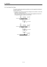
Program
Procedure to start up the power supply.
AC
(1) Set the CPU to RUN.
(2) Turn on the power supply.
(3) Turn on the start switch.
(4) Output equipment driven by program when the
electromagnetic contactor (MC) turns on.
AC and DC
(1) Set the CPU to RUN.
(2) Turn on the power supply.
(3) Turn ON RA2 when DC power supply is
established.
(4) Turn on timer (TM) when the DC power supply is
100% established. (Set TM set value to the time
from RA2 turning ON until the DC power supply
is 100% established. The set time should be
approximately 0.5 s.)
(5) Turn on the start switch.
(6) Output equipment driven by program when the
electromagnetic contactor (MC) turns on.
(When a voltage relay is used as RA2, the timer
(TM) in the program is not needed.)