


1. SPECIFICATIONS OF MOTION SYSTEM COMPONENTS
1
−
46
•
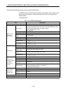
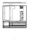
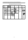
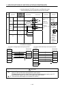
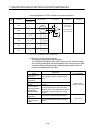
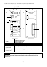
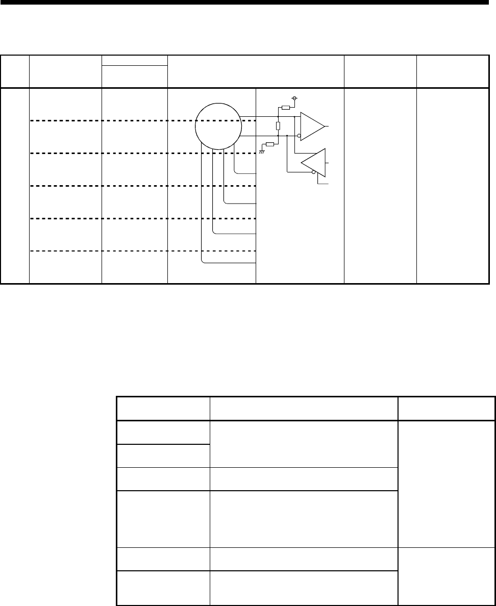
Interface between SY.ENC connector and external equipment
Pin No.
Input or
Output
Signal Name
SY.ENC
Connector
Wiring Example Internal Circuit Specification Description
MR
4
MRR
3
P5
*3
7, 8, 16
SG
*3
1, 2, 15, 17
BAT
14
Input
SD
20
•
Transmission
method: serial
communications
•
Position detection
method: absolute
*3: Connect when using MR-HSCBL10M to MR-HSCBL30M.
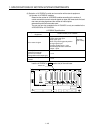
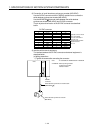
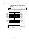
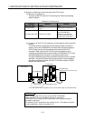
(c) Connection of servo external signals
There are the following servo external signals.
The A172SENC is assigned a set of input numbers per axis, with the exception
of the tracking enable signal and electromagnetic brake command output. Make
the system settings of the positioning software package to determine the I/O
numbers corresponding to the axis No.s.
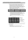
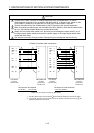
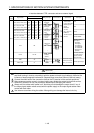
Servo External
Signal
Application
Number of Points on
One A172SENC
Upper stroke limit
input (FLS)
Lower stroke limit
input (RLS)
For detection of upper and lower stroke
limits
Stop signal input
(STOP)
For stopping under speed or positioning
control
Near-zero point
dog/speed-position
change input
(DOG/CHANGE)
For detection of near-zero point dog at
near-zero point dog or count type home
position return or for switching from speed
to position under speed-position change
control.
8 points each
(1 point/1 axis each)
Tracking enable
signal input
Synchronous encoder input start signal
Electromagnetic
brake command
output
For command output to electromagnetic
brake
1 point each
Serial
synchronous
encoder