


1. SPECIFICATIONS OF MOTION SYSTEM COMPONENTS
1
−
42
•
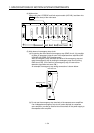
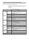
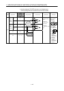
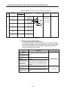
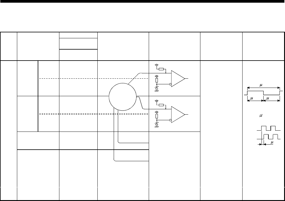
Interface between PULSER connector and voltage-output
manual pulse generator/incremental synchronous encoder
Pin No.
PULSER
Connector
Input or
Output
Signal Name
Voltage-Output
Type
Wiring Example Internal Circuit Specification Description
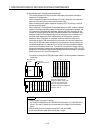
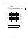
A
+
4
Manual
pulse
generator,
phase A
A
−
B
+
14
Manual
pulse
generator,
phase B
B
−
P5 6 16
SG 1 5 11 15
Input
•
Rated input
voltage 5.5 VDC
max.
•
HIGH level
3 VDC to 5.25
VDC/2 mA
•
LOW level
1 VDC max./ 5 mA
min.
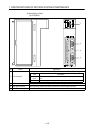
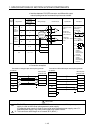
To connect manual
pulse generator
phases A,B
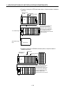
•
Pulse width
5 s min.
10 s min.
(Duty ratio:50%)
5 s min.
•
Rise, fall time
.......1
s max.
•
Phase difference
Phase A
Phase B
2.5 s min.
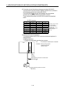
(1) Positioning
address
increases if
Phase A leads
Phase B.
(2) Positioning
address
decreases if
Phase B leads
Phase A.
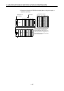
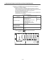
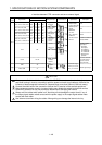
Manual pulse
generator/
synchronous
encoder
5V
0V
A
B
1K
1K