


5. INSPECTION AND MAINTENANCE
5
−
18
Table 5.7 Troubleshooting Input Circuits (cont.)
Symptom Cause Corrective Action
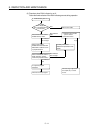
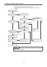
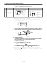
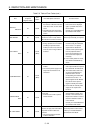
Example 5
Input signal does not
turn OFF
•
Sneak path due to use of two power supplies.
Input module
EE
E >E
12
12
•
Use a single power supply.
•
Connect a diode to prevent sneak paths, as
shown in the diagram.
Input module
L
E
12
E
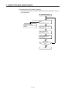
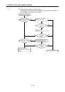
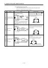
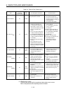
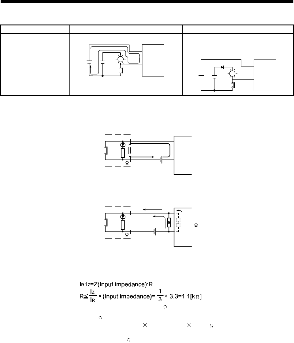
<Resistor Resistance Calculation for Example 4>
For the case with a limit switch with LED indicator connected to A1SX40,
causing 4 mA leak current.
Input module
4mA leak current
24VDC
A1SX40
3.6K
1) This circuit does not turn OFF because the A1SX40 OFF current of 1 mA is not
reached. Therefore, the connection of a resistor is required, as shown below.
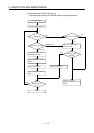
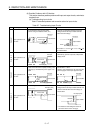
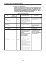
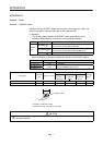
Input impedance
3.3K
24VDC
3.6K
I
R
=3mA
4mA
A1SX40
I
Z
=1mA
2) Resistance calculation
To achieve the A1SX40 OFF current of 1 mA, a resistor should be connected
such that a current of 3 mA min. flows through the resistor.
A resistance value of R < 1.1 k
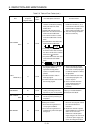
If a 1 k resistor is used, the resistor R power capacity (W) is given by:
W = (Current value)
2
R = 0.003
2
(A) 1000 ( ) = 0.009 (W)
3) In practice, a 1 [k
] 0.5 [W] resistor, which has a power capacity 3 to 5
times the actual power consumption, is connected across the terminals where
the problem exists.