


505429-JTG-F-1010
Johnson Controls Unitary Products 7
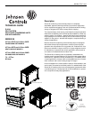
Condenser Motors
• Totally enclosed, air over cooled.
• Inherent overload protection.
• Permanently lubricated bearings.
• Must cycle to allow cooling operation down to 40°F.
Refrigerant Piping
• Solid core filter-drier(s) ship loose for field installation.
• Liquid and suction line service valves with gauge ports.
• Suction and discharge line service ports accessible
from unit. Ports capped for leak prevention.
• Liquid line magnetic check valves
• Holding charge of R410A refrigerant.
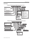
Electrical Requirements
• Single-point connection electrical power.
• Nominal unit electrical characteristics shall be _____ v,
3-ph, 60 Hz. The unit shall be capable of satisfactory
operation within voltage limits of ____ v to _____ v.
• Condenser fan motors and secondary of transformers
shall be grounded.
Unit Controls
• All 24-volt control circuit, powered by a 24 volt
transformer(s) and protected by a resettable breaker.
• Conventional thermostat must provide operation for
both condensing units and heat pumps without an “O”
output from the thermostat.
• Low voltage terminal strip for simple hook-up.
• Compressor motor protection shuts down unit for motor
over-current, over-temperature or low voltage
conditions.
• Safety lockouts provide reset capability at the space
thermostat or base unit should any of the following
standard safety devices trip and shut off compressor:
a. Loss-of-charge/Low-pressure switch.
b. High-pressure switch.
c. Control board diagnostics and fault code display.
d. Safety lockouts send a 24 volt signal to the control
board's "X" terminal, allowing notification to the user
via the thermostat fault light (if present).
e. Control board shall retain last 5 fault codes in non-
volatile memory, which will not be lost in the event of a
power loss. An LED (light-emitting diode) indicator
flashes a fault code that indicates which safety switch
has tripped.
Non-fused Disconnect Switch
• Factory-installed, internally mounted.
• Accessible from outside the unit.
• NEC and UL approved non-fused switch.
• Provides power off lockout capability.
Convenience Outlet
• Factory-installed, internally mounted.
• Accessible from outside the unit.
• 115V, 15 amp GFI receptacle with independent fuse
protection.
• Required voltage provided by factory-installed step-
down transformer or field supplied 115v circuit.
Low-ambient Head Pressure Control
• Standard operation down to 40 °F without a low
ambient kit.
• Operation down to 0°F with a field-installed low ambient
kit accessory. The controller modulates the fan motor
speed in response to liquid line temperature or
pressure.
Coil Guard
Factory or field installed decorative grille shall be placed on
the units to protect condenser coil after installation.
Hail Guard Package
Field installed hail guard package shall protect coils against
damage from hail and other flying debris.
Phenolic Coated Condenser Coils
Special phenolic coating available as a factory option on both
outdoor and indoor coils.
Each Unit Shall Be:
• Covered by a 1-year limited parts warranty on the
complete unit and 5-year on compressor(s).
• In current production with published literature available
to check performance, limitations, specifications, power
requirements, dimensions, operation and appearance.
• Indoor unit shall be equipped with a V-belt drive option
that will permit the blower RPM to be adjusted to meet
the CFM requirements of the air delivery system. (Refer