


505429-JTG-F-1010
6 Johnson Controls Unitary Products
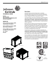
been mechanically expanded into aluminum fins. Both
headers are located on the same end of the coil. The coil is
leak-tested at 325 psig and dried before the connections are
capped for storage and shipping.
Guide Specifications
Split System Cooling Only Condensing Units
Models: J07 thru 25YC, J10 thru 20YD & Split
System Heat Pump Models: J07 thru 25PC, J15 thru
20PD
General
• Factory assembled, single piece, air cooled condensing
unit designed for outdoor installation.
• Factory wired, piped, and tested for leakage and
functionality to assure trouble-free installation and start-
up.
• Rated in accordance with ARI Standard 340/360.
• Manufactured in a facility registered under the ISO 9002
manufacturing quality standard.
• Designed and tested in accordance with ASHRAE 15
Safety Code for Mechanical Refrigeration and comply
with NEC.
• Cooling performance rated in accordance with DOE
and ARI test procedures.
• CSA listed and classified to UL 1995/CAN/CSA No.
236- M90 standards.
• One year limited parts warranty on complete unit with
an additional four year compressor warranty.
Unit Operating Characteristics
Operating Range shall be between 125° F to 40° F in cooling
as standard from factory.
• The capacity of the condensing unit shall meet or
exceed _____ Btuh at a suction temperature of _____
F. The power consumption at full load shall not exceed
_____ kW.
• The combination of the condensing unit and the
evaporator or fan coil unit shall have a total net cooling
capacity of _____ Btuh or greater at conditions of
_____ cfm entering-air temperature at the evaporator at
_____ F wet bulb and _____ F dry bulb, and air
entering the condensing unit at _____F.
• The system shall have an EER of _____ Btuh/ Watt or
greater at standard ARI conditions.
Installer Shall
• Furnish JCI® air-cooled condensing units, heat pump or
equivalent in accordance with the performance
schedule shown on the plans, and
• Unit shall be stored and handled in accordance with unit
manufacturer's instructions.
• Install each unit as shown on the plans in accordance
with the manufacturer’s recommendations and all
applicable national and local codes
Unit Construction
• Constructed of zinc-coated, galvanized steel.
• Exterior surfaces bonded and coated with baked
enamel finish by a powder paint process capable of
withstanding a minimum of 1000 salt spray hours
according to ASTM B117.
• Cabinet screws that comply with ASTM B117 salt spray
test for a minimum of 750 hours.
• Permanently attached heavy-gage perimeter base rails
with forklift slots and lifting holes.
• Removable access panels to all internal components.
• Separate access panel to controls.
• Access panels to allow outdoor coil cleaning.
Compressor(s)
• Hermetic scroll type, internally protected with high-
pressure relief and over temperature protection.
• Two stage units operate in 50% capacity increments.
• Suction gas cooled
• Voltage range of ±10% of unit nameplate voltage.
• Neoprene isolators minimize sound transmission and
vibration.
• Belly-band crankcase heaters keep refrigerant from
diluting sump oil.
• Full charge of compressor oil
Outdoor Condenser Unit Coils
• Draw thru configuration
• Constructed with Micro-channel aluminum fins and
aluminum tubing. All refrigerant tubing must share a
common header.
Heat Pump Unit Outdoor Unit Coils
• Draw thru configuration
• Constructed with aluminum plate fins mechanically
bonded to seamless internally enhanced copper tubes
with all joints brazed.
Condenser Fans
• Direct driven propeller-type fans
• Statically and dynamically balanced
• Aluminum blades riveted to corrosion resistant steel
spider brackets.
• Arranged for vertical air discharge.
• Equipped with PVC coated steel wire safety guards.