


505429-JTG-F-1010
110 Johnson Controls Unitary Products
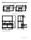
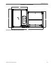
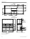
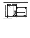
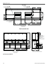
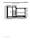
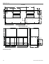
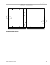
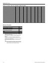
PIPING, ELECTRICAL AND DUCT OPENING CONNECTION SIZES
MODEL J07NC J10NC J10ND J15NC J15ND J20NC J20ND J25NC
SYSTEM DATA
No. Refrigeration Circuits 1 1 2 1 2 1 2 1
Suction Line OD (in.) 1 1/8 1 3/8 1 1/8 1 5/8 1 3/8 1 5/8 1 3/8 2 1/8
Liquid Line OD (in.) 5/8 7/8 5/8 7/8 5/8 7/8 7/8 7/8
Power Wiring Knockout 1 3/4 1 3/4 1 3/4 1 3/4 1 3/4 1 3/4 1 3/4 7/8
Control Wiring Knockout 7/8 7/8 7/8 7/8 7/8 7/8 7/8 7/8
Electric Heat Wiring Knockout 1 3/4 1 3/4 1 3/4 1 3/4 1 3/4 1 3/4 1 3/4 7/8
Drain Line Fitting PVC Stub 3/4 3/4 3/4 3/4 3/4 3/4 3/4
7/8
1
1
7/8 In Steel pipe
BLOWER OUTLET
Number 1 1 1 1 1 2 2 2
Width 13.4 15.9 15.9 18.9 18.9 15.9 15.9 22
Length 15.6 18.6 18.6 21.6 21.6 18.6 18.6 22
RETURN AIR INLET
Width 20.5 20.5 20.5 27.3 27.3 19.2 19.2 33.2
Length 52.0 52.0 52.0 71.9 71.9 93.4 93.4 95.6
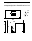
Minimum Clearances
Minimum Clearances
Top with Supply Air Opening
1
1
This dimension will vary if an electric heater, a supply air
plenum or a base is used.
24”
Front with Return Air Opening 24”
Right Side with access for Piping, Power &
Control Wiring Connections
2
2
This dimension is required for normal installation and
service.
24”
Left Side 24”
Rear
3
3
Although no clearance is required for service and
operation, some clearance may be required for routing
the power and control wiring.
N/A
Bottom
4
4
Allow enough clearance to trap the condensate drain
line.
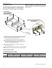
Note: If the coil has to be removed, the blower section
can be unbolted and set aside and the coil can be
lifted out the top of the evaporator section.
N/A