


70 • Chapter 4 - Software Tools and Communications DMC-1700/1800
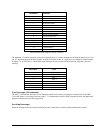
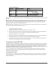
Secondary FIFO Registers
Operation Register (address) Value
Read N+2 Data Byte
Read N+3 Status Byte bit 0 = busy
bit 1 = freeze
bit 2 = not empty
Write N+2 Any Value - clears freeze bit
Write N+3 Any Value - sets freeze bit
Bit 0 (Busy Bit) - A ‘1’ signifies that the controller is still sending data to the FIFO. The controller sets this bit to 0 when
it is done.
Bit 1 (Freeze Bit) - When any value is written to the register N+3, this bit will be set to ‘1’ and the controller will send
the rest of the current record then stop sending data to the FIFO. When any value is written to the register N+2, the
freeze bit will be set to ‘0’ and the controller will resume its updates to the FIFO. The record must be frozen while
reading the record so that it does not change during the read.
Bit 2 (Not Empty Bit) - When this bit is set to ‘1’ by the controller, there is data in the FIFO to be read. After the entire
record has been read, the controller changes the bit to “0”.
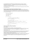
Polling FIFO Mode Read Procedure:
1. First, write any data to N+3 to “freeze” the data record. This sets bit 1 of N+3
2. Before the data record can be read, wait until the controller finishes updating the last data record by checking
the status of the busy bit (bit 0 of N+3) When bit 0 is 0, then the data record can be read.
3. Read a byte at address N+2. This is the data.
4. Repeat step 3 until all bytes of the data record have been read. Read each byte from N+2 while monitoring the
“Not Empty” bit (bit 2 of N+3). When Bit 2 is 0, the data record has been read completely.
5. After the entire record has been read, write any data to address N+2. This clears the freeze bit and allows the
controller to resume updating the data record with current data.
Communications with the DMC-1800
For main bi-directional communication, the DMC-1800 features a 512 character write FIFO buffer, and a 512 character
read buffer. This permits sending multiple commands at high speeds ahead of their actual processing by the DMC-1800.
The DMC-1800 also provides a secondary FIFO, for access to the data record. Additionally, the DMC-1800 provides
Dual Port RAM (DPRAM), which also allows access to the data record structure (DPRAM available on board Rev E and
greater DMC-1850 to 1880’s, and Rev H and greater DMC-1810 to 1840’s).
Note: This chapter provides an in-depth look at how the controller communicates over the PCI bus at the register
interface level. For most users, we recommend using the drivers supplied by Galil to provide the necessary tools for
communicating with the controller.
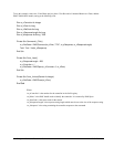
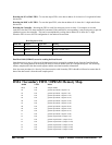
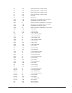
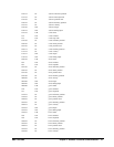
Determining the Base Address
The base address “N” is assigned its value by the BIOS and/or Operating System. The FIFO address N is referenced in
the PCI configuration space at BAR2 (offset 18H). The following PCI information (HEX) can be used to identify the
DMC-1800 controller: