


DMC-1700/1800 Chapter 3 Connecting Hardware • 45
All motion programs that are currently running are terminated when a transition in the Abort input is detected. For
information on setting the Off-On-Error function, see the Command Reference, OE.
Uncommitted Digital Inputs
The DMC-1700/1800 has 8 opto-isolated inputs. These inputs can be read individually using the function @ IN[x]
where x specifies the input number (1 thru 8). These inputs are uncommitted and can allow the user to create
conditional statements related to events external to the controller. For example, the user may wish to have the x-axis
motor move 1000 counts in the positive direction when the logic state of IN1 goes high
.
1X80
Controllers with more than 4 axes have 16 optoisolated inputs and 8 TTL inputs which are denoted as
Inputs 1 thru 24.
For controllers with more than 4 axes, the inputs 9-16 and the limit switch inputs for the additional
axes are accessed through the second 100-pin connector.
IN9-IN16 INCOM
FLE,RLE,HOMEE
FLF,RLF,HOMEF
FLG,RLG,HOMEG
FLH,RLH,HOMEH
LSCOM
This can be accomplished by connecting a voltage in the range of +5V to +28V into INCOM of the input circuitry
from a separate power supply
.
17X8
DMC-1718, 1728, 1738, 1748 controllers have 64 additional TTL I/O. The CO commands configures
each set of 8 I/O as inputs or outputs. The DMC-17X8 use two 50 pin headers which connect directly
via ribbon cable to an OPTO 22 (24 I/O) or Grayhill Opto rack (32 I/O).
The function “@IN[n]” (where n is 1-80) can be used to check the state of the inputs 1 thru 80.
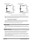
Wiring the Optoisolated Inputs
Bi-Directional Capability.
All inputs can be used as active high or low - If you are using an isolated power supply you can connect +5V to
INCOM or supply the isolated ground to INCOM. Connecting +5V to INCOM configures the inputs for active
low. Connecting ground to INCOM configures the inputs for active high.
INCOM can be located on the DMC-1700/1800 directly or on the ICM-1900 or AMP-19X0. The jumper is
labeled INCOM.
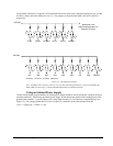
The optoisolated inputs are configured into groups. For example, the general inputs, IN1-IN8, and the
ABORT input are one group. Figure 3.1 illustrates the internal circuitry. The INCOM signal is a common
connection for all of the inputs in this group.
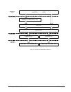
The optoisolated inputs are connected in the following groups
Group (Controllers with 1- 4 Axes) Group (Controllers with 5 - 8 Axes) Common
Signal
IN1-IN8, ABORT IN1-IN16, ABORT INCOM/INC*
FLX,RLX,HOMEX
FLY,RLY,HOMEY
FLZ,RLZ,HOMEZ
FLW,RLW,HOMEW
FLX,RLX,HOMEX,FLY,RLY,HOMEY
FLZ,RLZ,HOMEZ,FLW,RLW,HOMEW
FLE,RLE,HOMEE,FLF,RLF,HOMEF
FLG,RLG,HOMEG,FLH,RLH,HOMEH
LSCOM/LSC*