


190 • Chapter 10 Theory of Operation DMC-1700/1800
P/V = 1000/s
2
[rad/V]
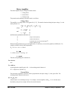
If the motor is a DC brushless motor, it is driven by an amplifier that performs the commutation. The combined
transfer function of motor amplifier combination is the same as that of a similar brush motor, as described by the
previous equations.
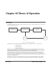
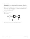
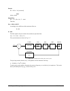
Velocity Loop
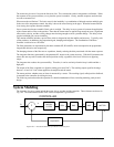
The motor driver system may include a velocity loop where the motor velocity is sensed by a tachometer and is fed
back to the amplifier. Such a system is illustrated in Fig. 10.5. Note that the transfer function between the input
voltage V and the velocity ω is:
ω /V = [K
a
K
t
/Js]/[1+K
a
K
t
K
g
/Js] = 1/[K
g
(sT
1
+1)]
where the velocity time constant, T1, equals
T1 = J/K
a
K
t
K
g
This leads to the transfer function
P/V = 1/[K
g
s(sT1+1)]
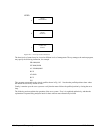
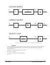
Σ
K
a
Kt/Js
K
g
V
Figure 10.5 - Elements of velocity loops
The resulting functions derived above are illustrated by the block diagram of Fig. 10.6.