


DMC-1700/1800 Chapter 6 Programming Motion • 121
Stepper Position Maintenance Mode (SPM)
The Galil controller can be set into the Stepper Position Maintenance (SPM) mode to handle the event
of stepper motor position error. The mode looks at position feedback from the main encoder and
compares it to the commanded step pulses. The position information is used to determine if there is
any significant difference between the commanded and the actual motor positions. If such error is
detected, it is updated into a command value for operator use. In addition, the SPM mode can be used
as a method to correct for friction at the end of a microstepping move. This capability provides closed-
loop control at the application program level. SPM mode can be used with Galil and non-Galil step
drives.
SPM mode is configured, executed, and managed with seven commands. This mode also utilizes the
#POSERR automatic subroutine allowing for automatic user-defined handling of an error event.
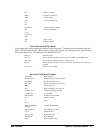
Internal Controller Commands (user can query):
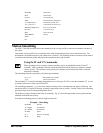
QS Error Magnitude (pulses)
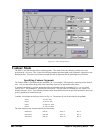
User Configurable Commands (user can query & change):
OE Profiler Off-On Error
YA Step Drive Resolution (pulses / full motor step)
YB Step Motor Resolution (full motor steps / revolution)
YC Encoder Resolution (counts / revolution)
YR Error Correction (pulses)
YS Stepper Position Maintenance enable, status
A pulse is defined by the resolution of the step drive being used. Therefore, one pulse could be a full
step, a half step or a microstep.
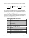
When a Galil controller is configured for step motor operation, the step pulse output by the controller
is internally fed back to the auxiliary encoder register. For SPM the feedback encoder on the stepper
will connect to the main encoder port. Enabling the SPM mode on a controller with YS=1 executes an
internal monitoring of the auxiliary and main encoder registers for that axis or axes. Position error is
then tracked in step pulses between these two registers (QS command).
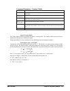
YC
YBYATP
TDQS
××
−=
Where TD is the auxiliary encoder register(step pulses) and TP is the main encoder register(feedback
encoder). Additionally, YA defines the step drive resolution where YA = 1 for full stepping or YA = 2
for half stepping. The full range of YA is up to YA = 9999 for microstepping drives.
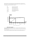
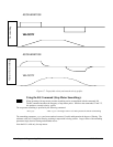
Error Limit
The value of QS is internally monitored to determine if it exceeds a preset limit of three full motor
steps. Once the value of QS exceeds this limit, the controller then performs the following actions: