


DMC-1700/1800 Chapter 4 - Software Tools and Communications • 67
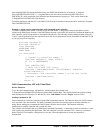
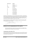
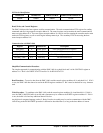
Status B
y
te
(
hex
)
Condition
00 No interrupt
D9 Watchdog timer activated
DA Command done
DB Application program done
F0 thru FF User interrupt
E1 thru E8 Input interrupt
C0 Limit switch occurred
C8 Excess position error
D8 All axis motion complete
D7 H axis motion complete
D6 G axis motion complete
D5 F axis motion complete
D4 E axis motion complete
D3 W axis motion complete
D2 Z axis motion complete
D1 Y axis motion complete
D0 X axis motion complete
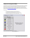
The Galil drivers and communication DLL’s will service the interrupt and return the StatusByte. Any host application
that has been properly configured though a window message will then be notified. When using the DMCShell control,
the windows message will be retrieved and the StatusByte will be returned as an argument. For example, when using the
ActiveX toolkit DMCShell control with VB, the DMCShell1_DMCInterrupt() event procedure (shown below) will
execute and pass the StatusByte in the argument. When an interrupt occurs, this StatusByte can then be used in a case
structure as the key to notify the host application of a specific event or condition.
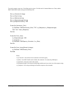
In the VB example below, the event procedure will display a message box every time the X-axis motion is complete,
assuming the command EI1 was sent to the controller. Note: the argument is returned as 208 since the status byte is
returned as an integer (i.e. D0 hex = 208 decimal).
Private Sub DMCShell1_DMCInterrupt(StatusByte As Integer)
If StatusByte = 208 Then
MsgBox "X axis complete"
End If
End Sub
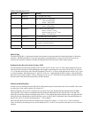
Hardware Level Communications for ISA and PCI
This section of the chapter describes in detail the structures used to communicate with the DMC-1700 and
DMC-1800 controllers at the register interface level. The information in this section is intended for advanced
programmers with extensive knowledge of ISA and PCI bus operation.
Communications with the DMC-1700
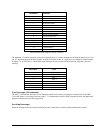
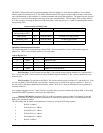
The DMC-1700 controller provides dual FIFO (first in first out) buffers, where a primary read/write FIFO is used for the
main command input and response, and a secondary FIFO is used for read-only access to the data record. The primary
read and write buffers are 512 characters deep, which permits sending multiple commands at high speeds ahead of their
actual command processing by the DMC-1700.