


DMC-1700/1800 Chapter 6 Programming Motion • 115
Command Summary - Contour Mode
COMMAND DESCRIPTION
CM XYZW
Specifies which axes for contouring mode. Any non-contouring axes may be operated in
other modes.
CM
ABCDEFGH
Contour axes for DMC-1780/1880
CD x,y,z,w
Specifies position increment over time interval. Range is +/-32,000. (Zero ends contour
mode, when issued following DT0.)
CD
a,b,c,d,e,f,g,h
Position increment data for DMC-1780/1880
DT n
Specifies time interval 2
n
msec for position increment, where n is an integer between 1 and
8. Zero ends contour mode. If n does not change, it does not need to be specified with each
CD.
WC Waits for previous time interval to be complete before next data record is processed.
General Velocity Profiles
The Contour Mode is ideal for generating any arbitrary velocity profiles. The velocity profile can be specified as a
mathematical function or as a collection of points.
The design includes two parts: Generating an array with data points and running the program.
Generating an Array - An Example
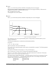
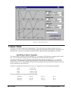
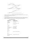
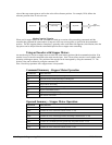
Consider the velocity and position profiles shown in Fig. 6.7. The objective is to rotate a motor a distance of 6000
counts in 120 ms. The velocity profile is sinusoidal to reduce the jerk and the system vibration. If we describe the
position displacement in terms of A counts in B milliseconds, we can describe the motion in the following manner:
()
ωπ
=−
Α
Β
Β12cos( )
Χ= −
AT
B
A
B
2
2
π
π
sin( )
Note: ω is the angular velocity; X is the position; and T is the variable, time, in milliseconds.
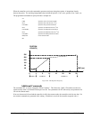
In the given example, A=6000 and B=120, the position and velocity profiles are:
X = 50T - (6000/2π) sin (2π T/120)
Note that the velocity, ω, in count/ms, is
ω = 50 [1 - cos 2π T/120]