


226 • Appendices DMC-1700/1800
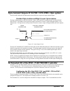
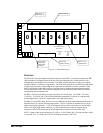
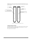
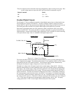
WARNING! Make sure that you do not connect the 100 pin cable from the IOM-1964 Rev. A to the
J1 motion I/O connector of the controller. Note the Error LED on the controller bracket to identify the
motion I/O connector.
Error LED
DMC-17x8
End bracket
100 pin high density connector J1
used for motion I/O
CB-50-80
End bracket
80 pin high density connector
used for extended I/O
Figure A.4 – CB-50-80 and CB-50-100 Bracket Layout
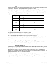
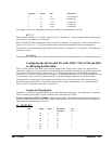
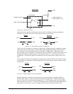
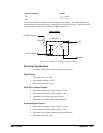
Configuring Hardware Banks
The extended I/O on the DMC-17x8 and DB-14064 is configured using the CO command. The banks
of buffers on the IOM-1964 are configured to match by inserting the appropriate IC’s and resistor
packs. The layout of each of the I/O banks is identical.
For example, here is the layout of bank 0: