


100 • Chapter 6 Programming Motion DMC-1700/1800
N=0 Initialize position increment
#LOOP LOOP
VX [COUNT]=N Fill Array VX
VY [COUNT]=N Fill Array VY
N=N+10 Increment position
COUNT=COUNT+1 Increment counter
JP #LOOP,COUNT<750 Loop if array not full
#A Label
LM XY Specify linear mode for XY
COUNT=0 Initialize array counter
#LOOP2;JP#LOOP2,_LM=0 If sequence buffer full, wait
JS#C,COUNT=500 Begin motion on 500
th
segment
LI VX[COUNT],VY[COUNT] Specify linear segment
COUNT=COUNT+1 Increment array counter
JP #LOOP2,COUNT<750 Repeat until array done
LE End Linear Move
AMS After Move sequence done
MG “DONE” Send Message
EN End program
#C;BGS;EN Begin Motion Subroutine
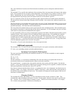
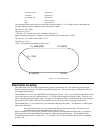
Vector Mode: Linear and Circular Interpolation Motion
The DMC-1700/1800 allows a long 2-D path consisting of linear and arc segments to be prescribed. Motion along
the path is continuous at the prescribed vector speed even at transitions between linear and circular segments. The
DMC-1700/1800 performs all the complex computations of linear and circular interpolation, freeing the host PC
from this time intensive task.
The coordinated motion mode is similar to the linear interpolation mode. Any pair of two axes may be selected for
coordinated motion consisting of linear and circular segments. In addition, a third axis can be controlled such that it
remains tangent to the motion of the selected pair of axes. Note that only one pair of axes can be specified for
coordinated motion at any given time.
The command VM m,n,p where ‘m’ and ‘n’ are the coordinated pair and p is the tangent axis (Note: the commas
which separate m,n and p are not necessary). For example, VM XWZ selects the XW axes for coordinated motion
and the Z-axis as the tangent.
Specifying the Coordinate Plane
The DMC-1700/1800 allows for 2 separate sets of coordinate axes for linear interpolation mode or vector mode.
These two sets are identified by the letters S and T.
To specify vector commands the coordinate plane must first be identified. This is done by issuing the command
CAS to identify the S plane or CAT to identify the T plane. All vector commands will be applied to the active
coordinate system until changed with the CA command.
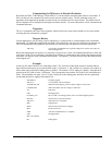
Specifying Vector Segments
The motion segments are described by two commands; VP for linear segments and CR for circular segments. Once
a set of linear segments and/or circular segments have been specified, the sequence is ended with the command VE.
This defines a sequence of commands for coordinated motion. Immediately prior to the execution of the first
coordinated movement, the controller defines the current position to be zero for all movements in a sequence. Note: