


188 • Chapter 10 Theory of Operation DMC-1700/1800
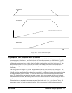
The results may be worse if we turn the faucet too fast. The overreaction results in temperature oscillations. When
the response of the system oscillates, we say that the system is unstable. Clearly, unstable responses are bad when
we want a constant level.
What causes the oscillations? The basic cause for the instability is a combination of delayed reaction and high gain.
In the case of the temperature control, the delay is due to the water flowing in the pipes. When the human reaction
is too strong, the response becomes unstable.
Servo systems also become unstable if their gain is too high. The delay in servo systems is between the application
of the current and its effect on the position. Note that the current must be applied long enough to cause a significant
effect on the velocity, and the velocity change must last long enough to cause a position change. This delay, when
coupled with high gain, causes instability.
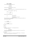
This motion controller includes a special filter which is designed to help the stability and accuracy. Typically, such
a filter produces, in addition to the proportional gain, damping and integrator. The combination of the three
functions is referred to as a PID filter.
The filter parameters are represented by the three constants KP, KI and KD, which correspond to the proportional,
integral and derivative term respectively.
The damping element of the filter acts as a predictor, thereby reducing the delay associated with the motor response.
The integrator function, represented by the parameter KI, improves the system accuracy. With the KI parameter, the
motor does not stop until it reaches the desired position exactly, regardless of the level of friction or opposing
torque.
The integrator also reduces the system stability. Therefore, it can be used only when the loop is stable and has a
high gain.
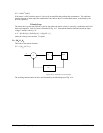
The output of the filter is applied to a digital-to-analog converter (DAC). The resulting output signal in the range
between +10 and -10 Volts is then applied to the amplifier and the motor.
The motor position, whether rotary or linear is measured by a sensor. The resulting signal, called position feedback,
is returned to the controller for closing the loop.
The following section describes the operation in a detailed mathematical form, including modeling,
analysis and
design.
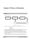
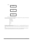
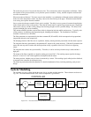
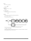
System Modeling
The elements of a servo system include the motor, driver, encoder and the controller. These elements are shown in
Fig. 10.4. The mathematical model of the various components is given below.
DIGITAL
FILTER
Σ
ZOH DAC
ENCODER
AMP MOTOR
CONTROLLER
R
C
X
Y
VE
P
Figure 10.4 - Functional Elements of a Motion Control System