


96 • Chapter 6 Programming Motion DMC-1700/1800
Additional Commands
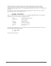
The commands VS n, VA n, and VD n are used to specify the vector speed, acceleration and deceleration. The
DMC-1700/1800 computes the vector speed based on the axes specified in the LM mode. For example, LM XYZ
designates linear interpolation for the X,Y and Z axes. The vector speed for this example would be computed using
the equation:
VS
2
=XS
2
+YS
2
+ZS
2
, where XS, YS and ZS are the speed of the X,Y and Z axes.
The controller always uses the axis specifications from LM, not LI, to compute the speed.
VT is used to set the S-curve smoothing constant for coordinated moves. The command AV n is the ‘After Vector’
trippoint, which halts program execution until the vector distance of n has been reached.
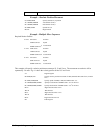
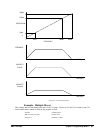
An Example of Linear Interpolation Motion:
#LMOVE label
DP 0,0 Define position of X and Y axes to be 0
LMXY Define linear mode between X and Y axes.
LI 5000,0 Specify first linear segment
LI 0,5000 Specify second linear segment
LE End linear segments
VS 4000 Specify vector speed
BGS Begin motion sequence
AV 4000 Set trippoint to wait until vector distance of 4000 is reached
VS 1000 Change vector speed
AV 5000 Set trippoint to wait until vector distance of 5000 is reached
VS 4000 Change vector speed
EN Program end
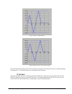
In this example, the XY system is required to perform a 90° turn. In order to slow the speed around the corner, we
use the AV 4000 trippoint, which slows the speed to 1000 count/s. Once the motors reach the corner, the speed is
increased back to 4000 cts / s.
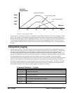
Specifying Vector Speed for Each Segment
The instruction VS has an immediate effect and, therefore, must be given at the required time. In some applications,
such as CNC, it is necessary to attach various speeds to different motion segments. This can be done by two
functions: < n and > m
For example: LI x,y,z,w < n >m
The first command, < n, is equivalent to commanding VSn at the start of the given segment and will
cause an acceleration toward the new commanded speeds, subjects to the other constraints.
The second function, > m, requires the vector speed to reach the value m at the end of the segment.
Note that the function > m may start the deceleration within the given segment or during previous
segments, as needed to meet the final speed requirement, under the given values of VA and VD.
Note, however, that the controller works with one > m command at a time. As a consequence, one
function may be masked by another. For example, if the function >100000 is followed by >5000, and
the distance for deceleration is not sufficient, the second condition will not be met. The controller will
attempt to lower the speed to 5000, but will reach that at a different point.
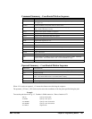
As an example, consider the following program.
#ALT Label for alternative program
DP 0,0 Define Position of X and Y axis to be 0
LMXY Define linear mode between X and Y axes.