


228 • Appendices DMC-1700/1800
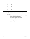
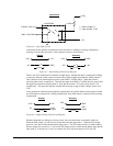
Input Circuit
1/4 NEC2505
To DMC-1748* I/O
DMC-1748* GND
1/8 RPx4
I/OC
n
I/O
n
x = bank number 0-7
n = input number 17-80
Connections to this optically isolated input circuit are done in a sinking or sourcing configuration,
referring to the direction of current. Some example circuits are shown below:
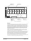
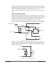
Sinking
Sourcing
+5V
GND +5V
GNDI/OC
n
I/OC
n
I/O
n
I/O
n
Current
Current
Figure A.7 – Input Sinking and Sourcing Diagram
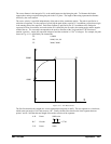
There is one I/OC connection for each bank of eight inputs. Whether the input is connected as sinking
or sourcing, when the switch is open no current flows and the digital input function @IN[n] returns 1.
This is because of an internal pull up resistor on the DMC-17x8/DB-14064*. When the switch is
closed in either circuit, current flows. This pulls the input on the DMC-17x8/DB-14064 to ground, and
the digital input function @IN[n] returns 0. Note that the external +5V in the circuits above is for
example only. The inputs are optically isolated and can accept a range of input voltages from 4 to 28
VDC.
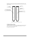
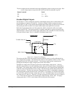
Active outputs are connected to the optically isolated inputs in a similar fashion with respect to current.
An NPN output is connected in a sinking configuration, and a PNP output is connected in the sourcing
configuration.
Sinking Sourcing
+5V
PNP
output
GND
I/OC
n
I/OC
n
I/O
n
I/O
n
Current
NPN
output
Current
Figure A.8 – Output Sinking and Sourcing Diagram
Whether connected in a sinking or sourcing circuit, only two connections are needed in each case.
When the NPN output is 5 volts, then no current flows and the input reads 1. When the NPN output
goes to 0 volts, then it sinks current and the input reads 0. The PNP output works in a similar fashion,
but the voltages are reversed i.e. 5 volts on the PNP output sources current into the digital input and the
input reads 0. As before, the 5 volt is an example, the I/OC can accept between 4-28 volts DC.
Figure A.6 – Opto Input Circuit