


178 • Chapter 8 Hardware & Software Protection DMC-1700/1800
a stop. If the Off-On-Error function is not enabled, the motor will instantaneously stop and servo at the current
position. The Off-On-Error function is further discussed in this chapter.
Selective Abort - The controller can be configured to provide an individual abort for each axis. Activation of the
selective abort signal will act the same as the Abort Input but only on the specific axis. To configure the controller
for selective abort, issue the command CN,,,1. This configures the inputs 5,6,7,8,13,14,15,16 to act as selective
aborts for axes A,B,C,D,E,F,G,H respectively.
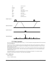
Forward Limit Switch - Low input inhibits motion in forward direction. If the motor is moving in the forward
direction when the limit switch is activated, the motion will decelerate and stop. In addition, if the motor is moving
in the forward direction, the controller will automatically jump to the limit switch subroutine, #LIMSWI (if such a
routine has been written by the user). The CN command can be used to change the polarity of the limit switches.
Reverse Limit Switch - Low input inhibits motion in reverse direction. If the motor is moving in the reverse
direction when the limit switch is activated, the motion will decelerate and stop. In addition, if the motor is moving
in the reverse direction, the controller will automatically jump to the limit switch subroutine, #LIMSWI (if such a
routine has been written by the user). The CN command can be used to change the polarity of the limit switches.
Software Protection
The DMC-1700/1800 provides a programmable error limit. The error limit can be set for any number between 1 and
32767 using the ER n command. The default value for ER is 16384.
Example:
ER 200,300,400,500
Set X-axis error limit for 200, Y-axis error limit to 300, Z-axis error limit to 400
counts, W-axis error limit to 500 counts
ER,1,,10 Set Y-axis error limit to 1 count, set W-axis error limit to 10 counts.
The units of the error limit are quadrature counts. The error is the difference between the command position and
actual encoder position. If the absolute value of the error exceeds the value specified by ER, the controller will
generate several signals to warn the host system of the error condition. These signals include:
Signal or Function State if Error Occurs
# POSERR Jumps to automatic excess position error subroutine
Error Light Turns on
OE Function Shuts motor off if OE1
AEN Output Line Goes low
The Jump on Condition statement is useful for branching on a given error within a program. The position error of
X,Y,Z and W can be monitored during execution using the TE command.
Programmable Position Limits
The DMC-1700/1800 provides programmable forward and reverse position limits. These are set by the BL and FL
software commands. Once a position limit is specified, the DMC-1700/1800 will not accept position commands
beyond the limit. Motion beyond the limit is also prevented.
Example:
DP0,0,0 Define Position
BL -2000,-4000,-8000 Set Reverse position limit
FL 2000,4000,8000 Set Forward position limit
JG 2000,2000,2000 Jog
BG XYZ Begin
(motion stops at forward limits)