


11-22
Cisco ONS 15454 Reference Manual, R8.5.x
78-18106-01
Chapter 11 Circuits and Tunnels
11.11 BLSR STS and VT Squelch Tables
• If BLSRs are provisioned as nonrevertive, PCA circuits are not restored automatically after a ring
or span switch. You must switch the BLSR manually.
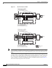
• PCA circuits are routed on working channels when you upgrade a BLSR from a two-fiber to a
four-fiber or from one optical speed to a higher optical speed. For example, if you upgrade a
two-fiber OC-48 BLSR to an OC-192, STSs 25 to 48 on the OC-48 BLSR become working channels
on the OC-192 BLSR.
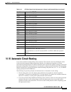
11.11 BLSR STS and VT Squelch Tables
ONS 15454 nodes display STS and VT squelch tables depending on the type of circuits created. For
example, if a fiber cut occurs, the BLSR squelch tables show STSs or VTs that will be squelched for
every isolated node. Squelching replaces traffic by inserting the appropriate alarm indication signal path
(AIS-P) and prevents traffic misconnections. For an STS with a VT-access check mark, the AIS-P will
be removed after 100 ms. To view the squelch tables, refer to the “Manage Circuits” chapter in the
Cisco ONS 15454 Procedure Guide for detailed instructions. For more information about BLSR
squelching, refer to Telcordia GR-1230.
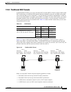
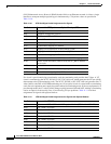
11.11.1 BLSR STS Squelch Table
BLSR STS squelch tables show STSs that will be squelched for every isolated node.
The BLSR Squelch Table window displays the following information:
• STS Number—Shows the BLSR STS numbers. For two-fiber BLSRs, the number of STSs is half
the BLSR OC-N, for example, an OC-48 BLSR squelch table will show 24 STSs. For four-fiber
BLSRs, the number of STSs in the table is the same as the BLSR OC-N.
• West Source—If traffic is received by the node on its west span, the BLSR node ID of the source
appears. (To view the BLSR node IDs for all nodes in the ring, click the Ring Map button.)
• West VT (from the West Source) — A check mark indicates that the STS carries incoming VT
traffic. The traffic source is coming from the west side.
• West VT (from the West Destination) — A check mark indicates that the STS carries outgoing VT
traffic. The traffic is dropped on the west side.
• West Dest—If traffic is sent on the node’s west span, the BLSR node ID of the destination appears.
• East Source—If traffic is received by the node on its east span, the BLSR node ID of the source
appears.
• East VT — (from the East Source) - A check mark indicates that the STS carries incoming VT
traffic. The traffic source is coming from the east side.
• East VT — (from the East Destination) - A check mark indicate that the STS carries outgoing VT
traffic. The traffic is dropped on the east side.
• East Dest—If traffic is sent on the node’s east span, the BLSR node ID of the destination appears.
Note BLSR squelching is performed on STSs that carry STS circuits only. Squelch table entries will not
appear for STSs carrying VT circuits or Ethernet circuits to or from E-Series Ethernet cards provisioned
in a multicard Ethergroup.