


5-29
Cisco ONS 15454 Reference Manual, R8.5.x
78-18106-01
Chapter 5 Ethernet Cards
5.12 CE-100T-8 Card
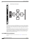
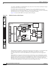
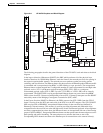
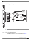
Figure 5-11 CE-100T-8 Faceplate and Block Diagram
The following paragraphs describe the general functions of the CE-100T-8 card and relate to the block
diagram.
In the ingress direction, (Ethernet-to-SONET), the PHY, which performs all of the physical layer
interface functions for 10/100 Mbps Ethernet, sends the frame to the network processor for queuing in
the respective packet buffer memory. The network processor performs packet processing, packet
switching, and classification. The Ethernet frames are then passed to the Ethermap where Ethernet traffic
is terminated and is encapsulated using HDLC or GFP framing on a per port basis. The encapsulated
Ethernet frames are then mapped into a configurable number of virtual concatenated low and high order
payloads, such as VT1.5 synchronous payload envelope (SPE), STS-1 SPE, or a contiguous
concatenated payload such as STS-3c SPE. Up to 64 VT1.5 SPEs or 3 STS-1 SPEs can be virtually
concatenated. The SONET SPE carrying encapsulated Ethernet frames are passed onto the qMDM
FPGA, where four STS-3 frames are multiplexed to form a STS-12 frame for transport over the SONET
network by means of the Bridging Convergence Transmission (BTC) ASIC.
In the Egress direction (SONET-to-Ethernet), the FPGA extracts four STS-3 SPEs from the STS-12
frame it receives from the BTC and sends each of the STS-3s to the ET3 mappers. The STS-3 SONET
SPE carrying GFP or PPP/HDLC encapsulated Ethernet frames is then extracted and buffered in
Ethermap’s external memory. This memory is used for providing alignment and differential delay
compensation for the received low-order and high-order virtual concatenated payloads. After alignment
and delay compensation have been done, the Ethernet frames are decapsulated with one of the framing
protocols (GFP or HDLC). Decapsulated Ethernet frames are then passed onto the network processor for
QoS queuing and traffic scheduling. The network processor switches the frame to one of the
corresponding PHY channels and then to the Ethernet port for transmission to the external client(s).
CE100T
8
FAIL
ACT
CONSOLE
1
2
3
4
5
6
7
8
134366
Packet Buffer
3x0.5MB
Control Mem
1x2MB
ETS
#1
SDRAM
qMDM
FPGA
Packet
Processor/
Switch
Fabric
qMDM
FPGA
Octal
PHY
SMII
8
8x
10/100BaseT
RJ45
Part of qMDM FPGA
FCC3
SMII
MII
4 SMII
STS3
STS3
STS3
ETS
#2
SDRAM
SDRAM
STS3
SCC1
60x
Flash
8MB
SDRAM
128MB
CPLD
SDRAM
1
4 SMII
ETS
#3
4 SMII
STS12
Add_Bus
Drop_Bus
ETS
#4
3 SMII
BTC
CPU
nVRAM
B
a
c
k
p
l
a
n
e
Option