


4-52
Cisco ONS 15454 Reference Manual, R8.5.x
78-18106-01
Chapter 4 Optical Cards
4.20.1 OC192SR1/STM64IO Short Reach and OC192/STM64 Any Reach Card-Level Indicators
4.20.1 OC192SR1/STM64IO Short Reach and OC192/STM64 Any Reach
Card-Level Indicators
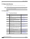
Table 4-25 describes the three card-level LEDs on the OC192SR1/STM64IO Short Reach and
OC192/STM64 Any Reach cards.
4.20.2 OC192SR1/STM64IO Short Reach and OC-192/STM-64 Any Reach
Port-Level Indicators
You can find the status of the OC192SR1/STM64IO Short Reach and OC192/STM64 Any Reach card
ports by using the LCD screen on the ONS 15454 fan-tray assembly. Use the LCD to view the status of
any port or card slot; the screen displays the number and severity of alarms for a given port or slot. Refer
to the Cisco ONS 15454 Troubleshooting Guide for a complete description of the alarm messages.
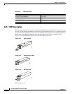
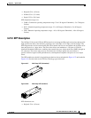
4.21 Optical Card SFPs and XFPs
The ONS 15454 optical cards use industry-standard SFPs and XFP modular receptacles.
Currently, the only optical cards that use SFPs and XFPs are the 15454_MRC-12, MRC-2.5G-4,
OC192SR1/STM64IO Short Reach, and OC192/STM64 Any Reach cards.
For all optical cards, the type of SFP or XFP plugged into the card is displayed in CTC and TL1. Cisco
offers SFPs and XFPs as separate orderable products.
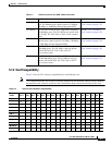
4.21.1 Compatibility by Card
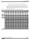
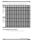
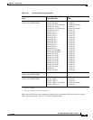
Table 4-26 lists Cisco ONS 15454 optical cards and their compatible SFPs and XFPs.
Caution Only use SFPs and XFPs certified for use in Cisco Optical Networking Systems (ONSs). The qualified
Cisco SFP and XFP pluggable module’s top assembly numbers (TANs) are provided in Table 4-26.
Table 4-25 OC192SR1/STM64IO Short Reach and OC192/STM64 Any Reach Card-Level Indicators
Card-Level LED Description
Red FAIL LED The red FAIL LED indicates that the card’s processor is not ready. This LED
is on during reset. The FAIL LED flashes during the boot process. Replace
the card if the red FAIL LED persists.
ACT/STBY LED
Green (Active)
Amber (Standby)
If the ACT/STBY LED is green, the card is operational and ready to carry
traffic. If the ACT/STBY LED is amber, the card is operational and in
standby (protect) mode or is part of an active ring switch (BLSR).
Amber SF LED The amber SF LED indicates a signal failure or condition such as LOS, LOF,
or high BERs on one or more of the card’s ports. The amber SF LED is also
on if the transmit and receive fibers are incorrectly connected. If the fibers
are properly connected and the link is working, the light turns off.