


1-67
Cisco ONS 15454 Reference Manual, R8.5.x
78-18106-01
Chapter 1 Shelf and Backplane Hardware
1.16 Alarm, Timing, LAN, and Craft Pin Connections
The ONS 15454 has redundant –48 VDC #8 power terminals on the shelf-assembly backplane. The
terminals are labeled BAT1, RET1, BAT2, and RET2 and are located on the lower section of the
backplane behind a clear plastic cover.
To install redundant power feeds, use four power cables and one ground cable. For a single power feed,
only two power cables (#10 AWG, 2.588 mm² [0.1018 inch], copper conductor, 194°F [90°C]) and one
ground cable (#6 AWG, 4.115 mm² [0.162 inch]) are required. Use a conductor with low impedance to
ensure circuit overcurrent protection. However, the conductor must have the capability to safely conduct
any faulty current that might be imposed.
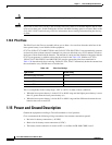
The existing ground post is a #10-32 bolt. The nut provided for a field connection is also a #10 AWG
(2.588 mm² [0.1018 inch]), with an integral lock washer. The lug must be a dual-hole type and rated to
accept the #6 AWG (4.115 mm² [0.162 inch]) cable. Two posts are provided on the Cisco ONS 15454 to
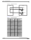
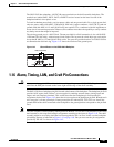
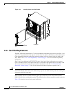
accommodate the dual-hole lug. Figure 1-41 shows the location of the ground posts.
Figure 1-41 Ground Posts on the ONS 15454 Backplane
1.16 Alarm, Timing, LAN, and Craft Pin Connections
Caution Always use the supplied ESD wristband when working with a powered ONS 15454. Plug the wristband
cable into the ESD jack located on the lower-right outside edge of the shelf assembly.
The ONS 15454 has a backplane pin field located at the bottom of the backplane. The backplane pin field
provides 0.045 square inch (29 mm
2
) wire-wrap pins for enabling external alarms, timing input and
output, and craft interface terminals. This section describes the backplane pin field and the pin
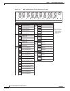
assignments for the field. Figure 1-42 shows the wire-wrap pins on the backplane pin field. Beneath each
wire-wrap pin is a frame ground pin. Frame ground pins are labeled FG1, FG2, FG3, etc. Install the
ground shield of the cables connected to the backplane to the ground pin that corresponds to the pin field
used.
Note The AIC-I requires a shelf assembly running Software Release 3.4.0 or later. The backplane of the ANSI
shelf contains a wire-wrap field with pin assignment according to the layout in Figure 1-42. The shelf
assembly might be an existing shelf that has been upgraded to R3.4 or later. In this case the backplane
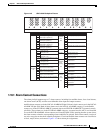
pin labeling appears as indicated in Figure 1-43 on page 1-69. But you must use the pin assignments
provided by the AIC-I as shown in Figure 1-42.
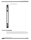
FRAME GROUND
61852
Attach #6 AWG