


5-36
Cisco ONS 15454 Reference Manual, R8.5.x
78-18106-01
Chapter 5 Ethernet Cards
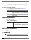
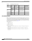
5.14.2 CE-MR-10 Port-Level Indicators
5.14.2 CE-MR-10 Port-Level Indicators
The CE-MR-10 card provides a pair of LEDs for each port: an amber LED for activity (ACT) and a green
LED for link status (LINK).
Table 5-28 describes the status that each color represents.
5.14.3 Cross-Connect and Slot Compatibility
The CE-MR-10 card can be installed in Slots 1 to 6 and 12 to 17 when used with the XC10G and
XC-VXC-10G cards. It is not compatible with the XVT card.
Caution Fan-tray assembly 15454-CC-FTA (ANSI shelf) must be installed in a shelf where a CE-MR-10 card is
installed.
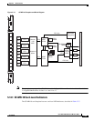
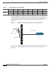
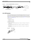
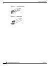
5.15 Ethernet Card GBICs and SFPs
This section describes the GBICs and SFPs used with the Ethernet cards.
The ONS 15454 Ethernet cards use industry standard SFPs and GBIC modular receptacles. The
ML-MR-10, ML100X-8, ML1000-2, and CE-MR-10 cards use standard Cisco SFPs. The Gigabit
E-Series, G-1K-4, and CE-1000-4 cards use standard Cisco GBICs. With Software Release 4.1 and later,
G-Series cards can also be equipped with dense wavelength division multiplexing (DWDM) and coarse
wavelength division multiplexing (CWDM) GBICs to function as Gigabit Ethernet transponders.
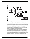
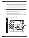
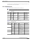
Table 5-27 CE-MR-10 Card-Level Indicators
Card-Level LEDs Description
FAIL LED (Red) The red FAIL LED indicates that the card processor is not ready or that a
catastrophic software failure occurred on the card. As part of the boot
sequence, the FAIL LED is turned on until the software deems the card
operational.
ACT LED (Green) The green ACT LED provides the operational status of the CE-1000-4 card.
When the ACT LED is green, it indicates that the CE-1000-4 card is active
and the software is operational.
Table 5-28 CE-MR-10 Port-Level Indicators
Port-Level Indicators Description
Off No link exists to the Ethernet port.
Steady amber A link exists to the Ethernet port, but traffic flow is inhibited. For
example, a lack of circuit setup, an error on the line, or a disabled port
might inhibit traffic flow.
Solid green A link exists to the Ethernet port, but no traffic is carried on the port.
Flashing green A link exists to the Ethernet port, and traffic is carried on the port. The
LED flash rate reflects the traffic rate for that port.