


4-9
Cisco ONS 15454 Reference Manual, R8.5.x
78-18106-01
Chapter 4 Optical Cards
4.3.1 OC3 IR/STM1 SH 1310-8 Card-Level Indicators
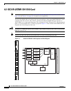
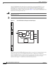
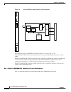
You can install the OC3 IR/STM1 SH 1310-8 card in Slots 1 to 4 and 14 to 17. The card can be
provisioned as part of a path protection or an ADM configuration. Each interface features a 1310-nm
laser and contains a transmit and receive connector (labeled) on the card faceplate. The card uses LC
connectors on the faceplate that are angled downward 12.5 degrees.
The OC3 IR/STM1 SH 1310-8 card supports 1+1 unidirectional and bidirectional protection switching.
You can provision protection on a per port basis.
The OC3 IR/STM1 SH 1310-8 card detects LOS, LOF, LOP, AIS-L, and RDI-L conditions. Refer to the
Cisco ONS 15454 Troubleshooting Guide for a description of these conditions. The card also counts
section and line BIP errors.
To enable APS, the OC3 IR/STM1 SH 1310-8 card extracts the K1 and K2 bytes from the SONET
overhead to perform appropriate protection switches. The OC3 IR/STM1 SH 1310-8 card supports full
DCC/GCC connectivity for remote network management.
4.3.1 OC3 IR/STM1 SH 1310-8 Card-Level Indicators
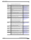
Table 4-4 describes the three card-level LEDs on the eight-port OC3 IR/STM1 SH 1310-8 card.
4.3.2 OC3 IR/STM1 SH 1310-8 Port-Level Indicators
Eight bicolor LEDs show the status per port. The LEDs show green if the port is available to carry traffic,
is provisioned as in-service, is part of a protection group, or is in the active mode. You can also find the
status of the eight card ports by using the LCD screen on the ONS 15454 fan-tray assembly. Use the LCD
to view the status of any port or card slot; the screen displays the number and severity of alarms for a
given port or slot. Refer to the Cisco ONS 15454 Troubleshooting Guide for a complete description of
the alarm messages.
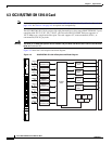
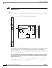
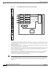
4.4 OC12 IR/STM4 SH 1310 Card
Note For hardware specifications, see the “A.6.3 OC12 IR/STM4 SH 1310 Card Specifications” section on
page A-30. See Table 4-2 on page 4-5 for optical card compatibility.
Table 4-4 OC3IR/STM1 SH 1310-8 Card-Level Indicators
Card-Level LED Description
Red FAIL LED The red FAIL LED indicates that the card’s processor is not ready. This LED
is on during reset. The FAIL LED flashes during the boot process. Replace
the card if the red FAIL LED persists.
Green ACT LED The green ACT LED indicates that the card is carrying traffic or is
traffic-ready.
Amber SF LED The amber SF LED indicates a signal failure or condition such as LOS, LOF,
AIS-L, or high BER on one or more of the card’s ports. The amber SF LED
is also on if the transmit and receive fibers are incorrectly connected. If the
fibers are properly connected and the links are working, the light turns off.