


2-15
Cisco ONS 15454 Reference Manual, R8.5.x
78-18106-01
Chapter 2 Common Control Cards
2.3.4 Power-Level Indicators
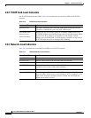
2.3.4 Power-Level Indicators
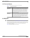
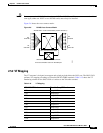
Table 2-12 describes the two power-level LEDs on the TCC2P faceplate.
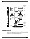
2.4 XCVT Card
Note For hardware specifications, see the “A.4.3 XCVT Card Specifications” section on page A-14.
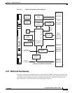
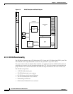
The Cross Connect Virtual Tributary (XCVT) card establishes connections at the STS-1 and VT levels.
The XCVT provides STS-48 capacity to Slots 5, 6, 12, and 13, and STS-12 capacity to Slots 1 to 4 and
14 to 17. Any STS-1 on any port can be connected to any other port, meaning that the STS
cross-connections are nonblocking.
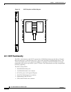
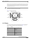
Figure 2-3 shows the XCVT faceplate and block diagram.
Table 2-12 TCC2P Power-Level Indicators
Power-Level LEDs Definition
Green/Amber/Red
PWR A LED
The PWR A LED is green when the voltage on supply input A is between the
low battery voltage (LWBATVG) and high battery voltage (HIBATVG)
thresholds. The LED is amber when the voltage on supply input A is between
the high battery voltage and extremely high battery voltage (EHIBATVG)
thresholds or between the low battery voltage and extremely low battery
voltage (ELWBATVG) thresholds. The LED is red when the voltage on
supply input A is above extremely high battery voltage or below extremely
low battery voltage thresholds.
Green/Amber/Red
PWR B LED
The PWR B LED is green when the voltage on supply input B is between the
low battery voltage and high battery voltage thresholds. The LED is amber
when the voltage on supply input B is between the high battery voltage and
extremely high battery voltage thresholds or between the low battery voltage
and extremely low battery voltage thresholds. The LED is red when the
voltage on supply input B is above extremely high battery voltage or below
extremely low battery voltage thresholds.