


4-27
Cisco ONS 15454 Reference Manual, R8.5.x
78-18106-01
Chapter 4 Optical Cards
4.12.1 OC48 ELR 100 GHz Card-Level Indicators
ONS 15216 100-GHz filters, the link budget is reduced by the insertion loss of the filters plus an
additional 2-dB power penalty. The wavelength stability of the OC48 ELR/STM16 EH 100 GHz cards
is +/– 0.12 nm for the life of the product and over the full range of operating temperatures. Each interface
contains a transmitter and receiver.
The OC48 ELR/STM16 EH 100 GHz cards detect LOS, LOF, LOP, and AIS-L conditions. The cards also
count section and line BIP errors.
4.12.1 OC48 ELR 100 GHz Card-Level Indicators
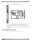
Table 4-13 lists the three card-level LEDs on the OC48 ELR/STM16 EH 100 GHz cards.
4.12.2 OC48 ELR 100 GHz Port-Level Indicators
You can find the status of the OC48 ELR/STM16 EH 100 GHz card ports by using the LCD screen on
the ONS 15454 fan-tray assembly. Use the LCD to quickly view the status of any port or card slot; the
screen displays the number and severity of alarms for a given port or slot.
4.13 OC48 ELR 200 GHz Cards
Note For hardware specifications, see the “A.6.12 OC48 ELR 200 GHz Card Specifications” section on
page A-38. See Table 4-2 on page 4-5 for optical card compatibility.
Eighteen distinct OC48 ELR 200 GHz cards provide the ONS 15454 DWDM channel plan. Each
OC48 ELR 200 GHz card provides one SONET OC-48 port that is compliant with Telcordia
GR-253-CORE. The port operates at 2.49 Gbps over a single-mode fiber span. The card carries VT,
concatenated (STS-1), or nonconcatenated (STS-3c, STS-6c, STS-12c, or STS-48c) payloads.
Warning
The laser is on when the optical card is booted. The port does not have to be in service for the laser
to be on.
Statement 293
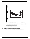
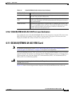
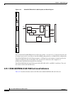
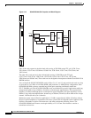
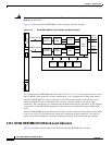
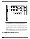
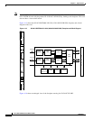
Figure 4-12 shows the OC48 ELR 200 GHz faceplate and a block diagram of the card.
Table 4-13 OC48 ELR/STM16 EH 100 GHz Card-Level Indicators
Card-Level Indicators Description
Red FAIL LED The red FAIL LED indicates that the card’s processor is not ready. Replace
the card if the red FAIL LED persists.
Green/Amber ACT
LED
The green ACT LED indicates that the card is carrying traffic or is
traffic-ready. The amber ACT LED indicates that the card is part of an active
ring switch (BLSR).
Amber SF LED The amber SF LED indicates a signal failure or condition such as LOS, LOF,
or high BERs on the card’s port. The amber SF LED is also on if the transmit
and receive fibers are incorrectly connected. If the fibers are properly
connected, the light turns off.