


5-30
Cisco ONS 15454 Reference Manual, R8.5.x
78-18106-01
Chapter 5 Ethernet Cards
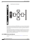
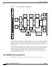
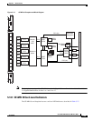
5.12.1 CE-100T-8 Card-Level Indicators
For information on the CE-100T-8 QoS features, refer to the “CE-100T-8 Operations” chapter of the
Cisco ONS 15454 and Cisco ONS 15454 SDH Ethernet Card Software Feature and Configuration
Guide.
5.12.1 CE-100T-8 Card-Level Indicators
The CE-100T-8 card faceplate has two card-level LED indicators, described in Table 5-23.
5.12.2 CE-100T-8 Port-Level Indicators
The CE-100T-8 card has two LEDs embedded into each of the eight Ethernet port RJ-45 connectors. The
LEDs are described in Table 5-24.
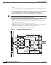
5.12.3 Cross-Connect and Slot Compatibility
The CE-100T-8 card is compatible in Slots 1 to 6 or 12 to 17 with the XC10G, XC-VXC-10G, or XCVT
cards.
5.13 CE-1000-4 Card
Note For hardware specifications, see the “A.7.5 CE-1000-4 Card Specifications” section on page A-50.
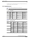
Table 5-23 CE-100T-8 Card-Level Indicators
Card-Level LEDs Description
SF LED (Red) The red FAIL LED indicates that the card processor is not ready or that a
catastrophic software failure occurred on the CE-100T-8 card. As part of the
boot sequence, the FAIL LED is turned on until the software deems the card
operational.
ACT LED (Green) The green ACT LED provides the operational status of the CE-100T-8. When
the ACT LED is green, it indicates that the CE-100T-8 card is active and the
software is operational.
Table 5-24 CE-100T-8 Port-Level Indicators
Port-Level Indicators Description
ACT LED (Amber) A steady amber LED indicates a link is detected, but there is an issue
inhibiting traffic. A blinking amber LED means traffic flowing.
LINK LED (Green) A steady green LED indicates that a link is detected, but there is no
traffic. A blinking green LED flashes at a rate proportional to the level
of traffic being received and transmitted over the port.
Both ACT and LINK LED
OFF
Unlit green and amber LEDs indicate no traffic.