


4-46
Cisco ONS 15454 Reference Manual, R8.5.x
78-18106-01
Chapter 4 Optical Cards
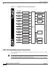
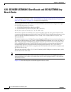
4.18.4 15454_MRC-12 Port-Level Indicators
4.18.4 15454_MRC-12 Port-Level Indicators
Each port has an Rx indicator. The LED flashes green if the port is receiving a signal, and it flashes red
if the port is not receiving a signal.
You can also find the status of the 15454_MRC-12 card ports by using the LCD screen on the ONS 15454
fan-tray assembly. Use the LCD to view the status of any port or card slot; the screen displays the number
and severity of alarms for a given port or slot. Refer to the Cisco ONS 15454 Troubleshooting Guide for
a complete description of the alarm messages.
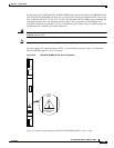
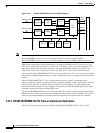
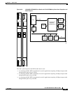
4.19 MRC-2.5G-4 Multirate Card
Note For hardware specifications, see the “A.6.17 15454_MRC-12 Card Specifications” section on
page A-44. See Table 4-2 on page 4-5 for optical card compatibility.
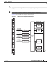
The MRC-2.5G-4 multirate card provides up to four OC-3/STM-1 ports, four OC-12/STM-4 ports, or
one OC-48/STM-16 ports using small form-factor pluggables (SFPs), in various combinations of line
rates. All ports are Telcordia GR-253 compliant. The SFP optics can use SR, IR, LR, coarse wavelength
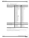
division multiplexing (CWDM), and DWDM SFPs to support unrepeated spans. See the “4.21 Optical
Card SFPs and XFPs” section on page 4-52 for more information about SFPs.
The ports operate at up to 2488.320 Mbps over a single-mode fiber. The MRC-2.5G-4 card has four
physical connector adapters with two fibers per connector adapter (Tx and Rx). The card supports VT
payloads, STS-1 payloads, and concatenated payloads at STS-3c, STS-6c, STS-9c, STS-12c, STS-18c,
STS-24c, STS-36c, or STS-48c signal levels. It is fully interoperable with the ONS 15454 G-Series
Ethernet cards.
Each MRC-2.5G-4 port contains a transmit and receive connector (labeled) on the card faceplate. The
card supports 1+1 unidirectional and bidirectional facility protection. It also supports 1+1 protection in
four-fiber BLSR applications where both span switching and ring switching might occur. You can
provision this card as part of an BLSR, path protection, or 1+1 linear configuration. The MRC-2.5G-4
card also supports optimized 1+1 protection when used with OC-3 SFPs.
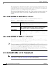
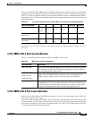
Table 4-21 15454_MRC-12 Card-Level Indicators
Card-Level LED Description
Red FAIL LED The red FAIL LED indicates that the card’s processor is not ready. This LED
is on during reset. The FAIL LED flashes during the boot process. Replace
the card if the red FAIL LED persists.
ACT/STBY LED
Green (Active)
Amber (Standby)
If the ACT/STBY LED is green, the card is operational and ready to carry
traffic. If the ACT/STBY LED is amber, the card is operational and in
standby (protect) mode or is part of an active ring switch (BLSR).
Amber SF LED The amber SF LED indicates a signal failure or condition such as LOS, LOF,
or high BERs on one or more of the card’s ports. The amber SF LED is also
on if the transmit and receive fibers are incorrectly connected. If the fibers
are properly connected and the link is working, the light turns off.