


11-11
Cisco ONS 15454 Reference Manual, R8.5.x
78-18106-01
Chapter 11 Circuits and Tunnels
11.2.5 Circuit Information in the Edit Circuit Window
• Alarm states of nodes on the circuit route
• Number of alarms on each node organized by severity
• Port service states on the circuit route
• Alarm state/color of most severe alarm on port
• Loopbacks
• Path trace states
• Path selector states
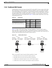
By default, the working path is indicated by a green, bidirectional arrow, and the protect path is indicated
by a purple, bidirectional arrow. Source and destination ports are shown as circles with an S and D. Port
states are indicated by colors, shown in Table 11-4.
In detailed view, a notation within or by the squares or selector pentagons indicates switches and
loopbacks, including:
• F = Force switch
• M = Manual switch
• L = Lockout switch
• Arrow = Facility (outward) or terminal (inward) loopback
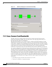
Move the mouse cursor over nodes, ports, and spans to see tooltips with information including the
number of alarms on a node (organized by severity), the port service state, and the protection topology.
Right-click a node, port, or span on the detailed circuit map to initiate certain circuit actions:
• Right-click a unidirectional circuit destination node to add a drop to the circuit.
• Right-click a port containing a path-trace-capable card to initiate the path trace.
• Right-click a path protection span to change the state of the path selectors in the path protection
circuit.
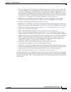
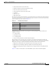
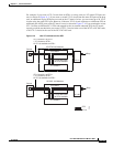
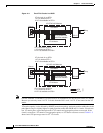
Figure 11-2 shows a circuit routed on a two-fiber BLSR. A port is shown in terminal loopback.
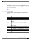
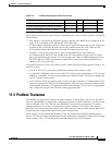
Table 11-4 Port State Color Indicators
Port Color Service State
Green IS-NR
Gray OOS-MA,DSBLD
Violet OOS-AU,AINS
Blue (Cyan) OOS-MA,MT