


1-60
Cisco ONS 15454 Reference Manual, R8.5.x
78-18106-01
Chapter 1 Shelf and Backplane Hardware
1.12.1 Wire-Wrap and Pin Connections
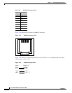
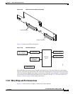
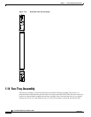
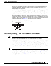
Figure 1-39 is a circuit diagram of the alarm outputs (Outputs 1 and 16 are shown in the example).
Figure 1-39 Alarm Output Circuit Diagram
Use the pin numbers in Table 1-26 to connect to the external elements being switched by external alarms.
20 GND 46 ALARM_IN_26–
21 ALARM_IN_27– 47 ALARM_IN_28–
22 ALARM_IN_29– 48 GND
23 GND 49 ALARM_IN_30–
24 ALARM_IN_31– 50 N.C.
25 ALARM_IN_+ 51 GND1
26 ALARM_IN_0– 52 GND2
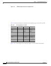
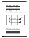
Table 1-25 Alarm Input Pin Association (continued)
AMP Champ
Pin Number Signal Name
AMP Champ
Pin Number Signal Name
78474
Station
max. 60 V/100 mA
AEP/AIE
Output 1
Output 16
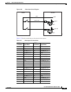
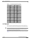
Table 1-26 Pin Association for Alarm Output Pins
AMP Champ
Pin Number Signal Name
AMP Champ
Pin Number Signal Name
1N.C. 27COM_0
2 COM_1 28 N.C.
3 NO_1 29 NO_2
4N.C. 30COM_2
5 COM_3 31 N.C.
6 NO_3 32 NO_4