


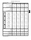
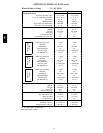

64
de--energized as the dampers close below the PE--On
setpoint.
Damper movement from full closed to full open (or vice
versa) will take between 1
1
/
2
and 2
1
/
2
minutes.
Heating With EconoMi$er IV
During Oc cupied mode operation, indoor fan operation
will be accompanied by economizer dampers moving to
Minimum Position setpoint fo r ventilation. If indoor fan is
off, dampers will close. During Unoccupie d mode
operation, dampers will remain closed unless a DCV
demand is received.
When the room temperature calls for heat (W1 closes), the
heating controls are energized as describe d in Heating,
Unit Without Economizer above .
Defrost Cycle
During the Heating Mode, frost and ice can develop on
the out door coil. Defrost sequence will clear the frost and
ice from the coil by briefly reversing the Heating
sequence periodically.
A window to test for a need to run the Defrost cycle opens
30 minutes after the end of the last Defrost cycle or the
previous test window closed. If DFT2 is closed, the
Defrost cycle will start. Output a t OF is removed; outdoor
fans stop during the Defrost cycle. Output P3--6 (RVS2) is
energized; reversing valve solenoid RVS2 is energized and
reversing valve 2 cha nges position, placing Circuit 2 in a
Cooling m ode flow, directing hot gas into the outdoor coil
where its heat melts the frost and looses the ice on the coil
face.
During the Defrost cycle, output EHEAT is also energized
(if not already energized by a thermostat W2 demand);
electric heaters will be energized.
During the Defrost Cycle, LED1 on the DFB wil l be
illuminated.
The Defrost cycle ends when DFT2 opens (as liquid
temperature exiting the coil rises above DFT2 setpoint) or
the defrost c ycle runs for 10 minutes. Output at EHEAT is
removed; electric heaters will be de--energized (unless
thermostat has a W2 demand). Output at OF is restored;
outdoor fans start again. Output at P3--6 (RVS2) is
removed; reversing valve 2 returns to Heating position.
During the Circuit 2 defrost cycle, Circuit 1 may also
enter defrost cycle if DFT1 closes. When DFT1 closes,
DFB output P3--7 (RVS1) is energized; reversing valve
solenoid 1 is energized, causing reversing valve 1 to
switch position and place Circuit 1 in a Cooling mode
flow. Defrost in Circuit 1 ends when DFT1 opens or
defrost cycle in Circuit 2 is terminated.
Defrost cycle is fixed at a maximum 10 minute duration
limit. The period to test and initiate a Defrost cycle can be
selec ted at 30, 60, 90 or 120 minutes.
Emergency Heat
Emergency Heat is a non--staged heating cycle that uses
the unit’s electric heaters only (no compression heating is
energized). Emergency Heat is initiated when the defrost
board receives a n i nput signal at W2 (P2--6) but there is
no input signal at W1 (P2--7). This signal combination can
be provided by thermostat configuration, manual external
switch selection or by servicer disconnecting the W1 field
connec tion.
Upon initiation of the Emergency Heat sequence, the DFB
will issue output signals at IFO (P3--9) and EHEAT; IFM
will run and electric heaters will be energized.
When space heating load is satisfied, the input signal at
W2 (P2--6) will be removed. Output at EHEAT is
removed; electric heaters are de--energized. After the Fan
Delay period, the signal at IFO (P3--9) is removed; IFM
stops.
Demand Controlled Ventilation
If a field--installed sensor is connected to the EconoMi$er
IV control, a Demand Controlled Ventilation strategy will
operate automatically. As the level in the space increases
above the setpoint (on the EconoMi$er IV controller), the
minimum position of the dampers will be increased
proportionally, until the Maximum Ventilation setting is
reached. As the space level decreases because of the
increase in fresh air, the outdoor--damper will follow the
higher demand condition from the DCV mode or from the
free--cooli ng mode.
DCV operation is availabl e in Occupied and Unoc cupied
periods with EconoMi$er IV. However, a control
modification will be required on the 50TC unit to
implement the Unoccupied period function.
Supplemental Controls
Compressor Lockout Rel ay (CLO) – The CLO is available
as a factory-installed option or as a field-installed
accessory. Each compressor has a CLO. The CLO
compares the demand for compressor operation (via a
24-v input from Y at CLO terminal 2) to operation of the
compressor (determined via compressor current signal
input at the CLO’s current tra nsformer loop); if the
compressor current signal is lost while the demand input
still exists, the CLO will trip open and prevent the
compressor from restarting until the CLO has been
manually reset. In the lockout condition, 24-v will be
available at terminal X. Reset is accomplished by
removing the input signal at terminal 2; open the
thermostat briefly or cycle the main power to the unit.
Phase Monitor Relay (PMR) – The PMR protects the unit
in the event of a loss of a phase or a r eversa l of power l ine
phase in the three-phase unit power supply. In normal
operation, the relay K1 is energized (contact set closed)
and red LED indica tor is on steady. If the PMR detects a
loss of a pha se or a phase sequence reversal, the relay K1
is energized, its contact set i s opened and unit operation is
stopped; red LED indicator will blink during lockout
condition. Reset of the PMR is automatic when all phases
548J