


20
if the GFCI receptacle does not trip as required. Press the
RESET but ton t o clear the tripped condition.
CO8283
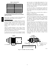
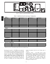
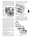
UNIT
VOLTAGE
CONNECT
AS
PRIMARY
CONNECTIONS
TRANSFORMER
TERMINALS
208,
230
240
L1: RED +YEL
L2: BLU + GRA
H1 + H3
H2 + H4
460 480
L1: RED
Splice BLU + Y EL
L2: GRA
H1
H2 + H3
H4
575 600
L1: RED
L2: GRA
H1
H2
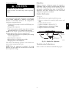
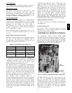
Fig. 24 -- Powered Convenience Outlet Wi ring
Maintenance: Periodically test the GFCI receptacle by
pressing the TEST button on the face of the receptacle.
This should cause the interna l circuit of the receptacle to
trip and open t he receptacle. Check for proper grounding
wires and power line phasing if the GFCI receptacle does
not trip as required. Press the RESET butt on to clear the
tripped condition.
Fuse on powered type: The factory fuse is a Bussman
“Fusetron” T--15, non--renewable screw--in (Edison base)
type plug fuse.
Using unit--mount ed convenience outlets: Units with
unit--mounted convenience outlet circuit s will often
require that two disconnects be opened to de--energize al l
power to the unit. Treat all units as electrically energized
until the convenience outlet power is also c hecked and
de--energization is confirmed. Observe National Electrical
Code Article 210, Branc h Circuit s, for use of c onvenience
outlets.
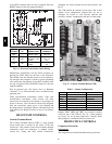
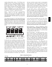
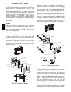
HEAT PUMP CONTROLS
Controls Terminal B oard
The Controls Terminal Board (CTB) is a large printed
circuit board that is located in the center of the unit
control box. This printed circuit board contains multiple
termination strips and connectors to simplify factory
control box wiring and field control connections.
Terminals are clearly marked on the board surface. See
Fig 25.
The CTB contains no software and no logic. But it does
include seven configuration jumpers that are cut to
configure the board to read external optional and
accessory controls, including that the unit is a heat pump.
C09274
Fig. 25 -- Controls Terminal Boar d (CTB)
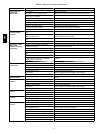
Table 7 – Jumper Configuration
Jumper Control Function Note
JMP1 Phase Monitor
JMP2 Occupancy Control
JMP3 Smoke Detector Shutdown
JMP4 Remote Shutdown
JMP5 Heat Pu mp / Reheat 548J default: Cut
JMP6 Heat Pu mp / Reheat 548J default: Cut
JMP7 Heat Pu mp / Reheat 548J default: Cut
Jumpers JMP5, JMP6 and JMP7 are located in notches
across the top of the CTB (see Fig. 25 ). The se jumpers
are factory cut on all heat pump units. Visually check
these j umpers to confi rm that they ha ve been cut.
PROTECTIVE CONTROLS
Compressor Protection
Overcurrent
The compressor has internal linebreak motor protection.
548J