


28
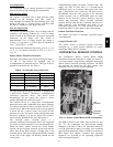
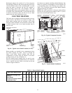
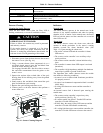
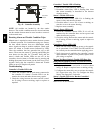
6. For units with an economizer, the sampling tube is in-
tegra ted into the economizer housing but the connec-
tion of the flexible tubing to the sampling tube is the
same.
C08127
Fig. 41 -- Return Air Sensor Operating Position
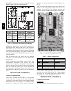
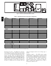
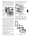
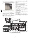
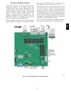
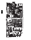
FIOP Sm oke Detector Wiring and Response
All units: FIOP smoke detector is configured to
automatically shut down all unit operations when smoke
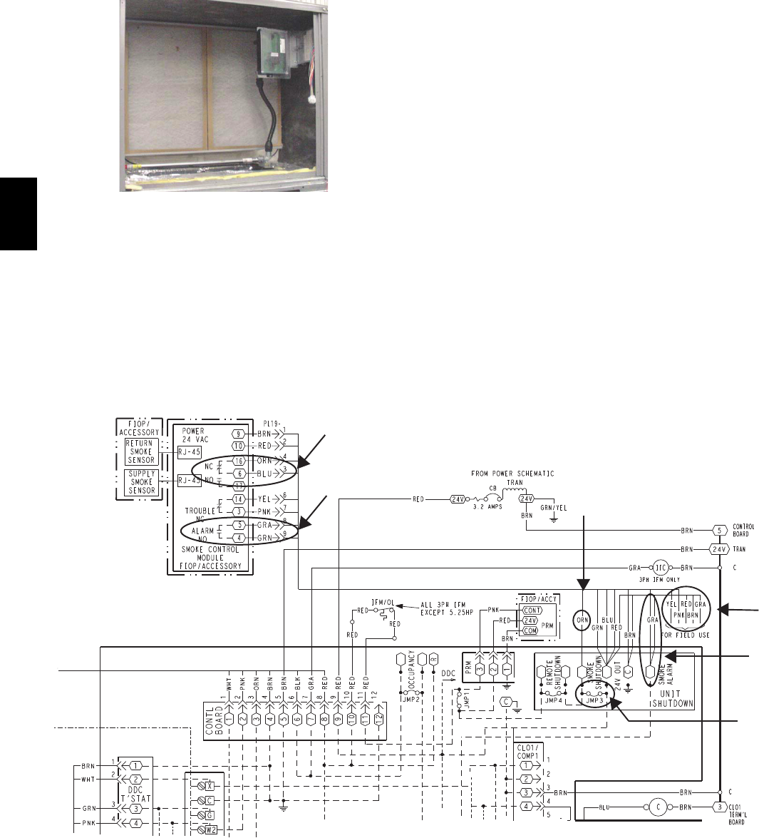
condition is detected. See Fig. 42, Typical Smoke
Detector System Wiring.
Highlight A: JMP 3 is factory--cut, transfe rring unit
control to smoke detector.
Highlight B: Smoke detector NC contact set will open on
smoke ala r m condition, de--energizing the ORN
conduct or.
Highlight C: 24--v power signal via ORN lead is removed
at Smoke Detector input on CTB (Control Terminal
Board); all unit operations cease immediately.
Highlight D: On smoke alarm condition, the smoke
dete ctor NO Alarm contact will close, supplying 24--v
power to GRA conductor.
Highlight E: GRA lead at Smoke Alarm input on CTB
provides 24--v signal to FIOP DDC control.
RTU--MP: The 24--v signal is conveyed to RTU--MP’s
J1-- 10 input terminal. This signal initiates the FSD
sequence by the RTU--MP control. FSD status is reported
to connected BAS network.
Using Re mote Logic: Five conductors are provided for
field use (see Highlight F in Fig. 42) for additional
annunci ation functions.
Additional Application Data — Refer to Catalog No.
HKRNKA--1XA for discussions on additional control
features of these smoke detectors including multiple unit
coordina tion. See Fig. 42.
A
E
F
C
D
B
C08246
Fig. 42 -- Typical Smoke Detector System Wiring
548J