


11
To
Evaporato
r
Coil
Circuits
From
Liquid
Header
Metering
Orifice
C09229
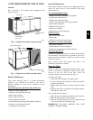
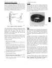
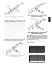
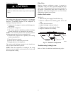
Fig. 15 -- Heat Pump Acutrol — Flow as Evaporator
Function
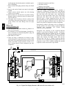
Converging circuit flow in the condenser--function
operation is accomplished with the check valve in the
vapor header and the liquid transfer header connected to
the side ports on all but one of the Acurator te e nipples in
each circuit. During condenser--function ope ration, hot gas
from the compressor discharge enters the header until it
reaches the check valve which blocks further flow. The
hot gas exits the header through the tubes above the check
valve and enters these coil circuits. At the outlet of these
desuperhea ting and condensing circuits, the refrigerant
enters the Acurater tees from the coil end. The r efrigerant
exits the tee at the side port and enters the liquid transfer
heade r (see Fig. 16). The refrigerant moves through the
liquid transfer header and exit s through the remaining
tubes, through the side ports on the Acutrol tees (see
Fig. 17) and back into the coil circuits where additional
condensing occurs. These circuits exit into the vapor
heade r behind the check valve and exit through the
rema ining tube on the vapor header. In this last pass
through the coil, the refrigerant is subcooled. Subcooled
liquid exits at the last Acutrol tee (see Fig. 18) where the
side port is connected to the specific mode liquid line.
From
Condenser
Coil Circuits
To
Transfer
Header
C09230
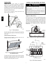
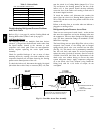
Fig. 16 -- Heat Pump Acutrol — Flow as Condenser
Function/Exiting First Pass
To
Condensing
Circuit
From
Transfer
Header
C09231
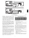
Fig. 17 -- Heat Pump Acutrol — Flow as Condenser
Function/Entering Second Pass
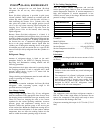
From
Subcoole
r
Circuit
To
Liquid
Line
DFT Location
(Outdoor Coils only)
C09232
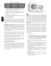
Fig. 18 -- Heat Pump Acutrol — Flow as Condenser
Function/Ex iting Subcooler Pass
Eac h liquid line has a check valve to prevent backflow
through the liquid line in its opposite mode. Thi s ensures
correct flow direction through filter driers and strainers
and prevents emptying of off -- mode liquid lines into
evapora tor--function coil circuits.
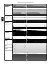
Reversing Valve and Ch eck Valve Position
SeeFig.14onpage10.
Table 3 – Cooling Mode (each circuit)
Component Status/Position
Reversing Valve Energized
Check Valve A Closed
Check Valve B Open
Check Valve C Closed
Check Valve D Open
Table 4 – Heating Mode (each circuit )
Component Status/Position
Reversing Valve De---energized
Check Valve A Open
Check Valve B Closed
Check Valve C Open
Check Valve D Closed
548J