


38
SEN
SEN
J20-1
J20-2
C08460
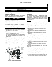
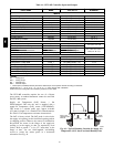
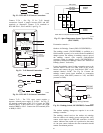
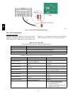
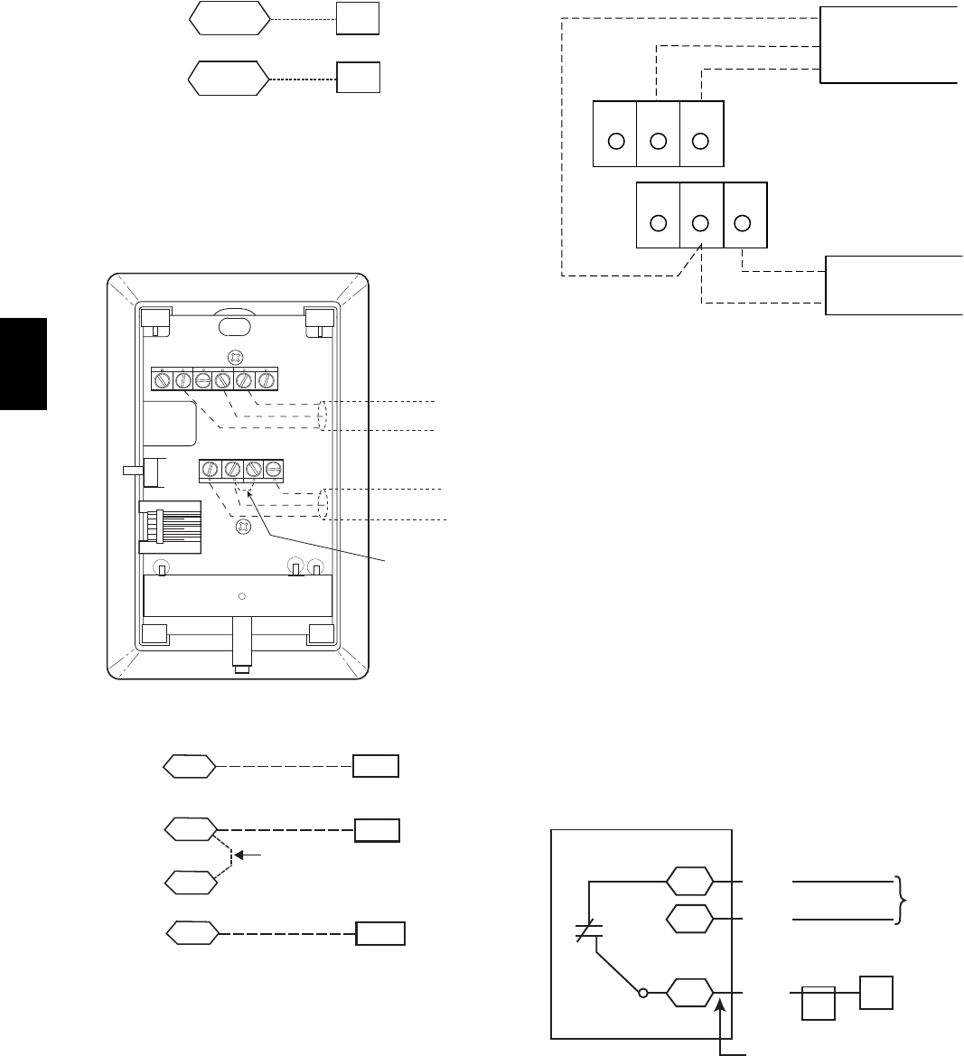
Fig. 52 -- RTU--MP T--55 Sensor Connections
Connect T--56 -- See Fig. 53 for T--56 internal
connec tions. Install a jumper between SEN and SET
terminals as illustrated. Connect T --56 terminals to
RTU--MP J20--1, J20--2 and J20--3 per Fig. 54.
2
3
45
61
SW1
SEN
SET
Cool Warm
BRN (GND)
BLU (SPT)
RED(+)
WHT(GND)
BLK(-)
CCN COM
SENSOR WIRING
JUMPER
TERMINALS
AS SHOWN
BLK
(T56)
C08202
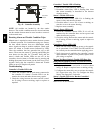
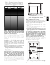
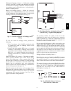
Fig. 53 -- T--56 Internal Connections
SEN J20-1
J20-2
SEN
SET
Jumper
J20-3
SET
C08461
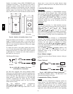
Fig. 54 -- RTU--MP T--56 Sensor Connections
Connect T--59 -- The T--59 space se nsor requires a
separat e, isolated power supply of 24 VAC. See Fig. 55
for internal connections at the T--59. Connect the SE N
terminal (BLU) to RTU--MP J20--1. Connect the COM
terminal (BRN) to J20--2. Connect the SET terminal (STO
or BLK) to J20--3.
OR SET SEN
OPB COM- PWR+
BLU (SPT)
BLK (STO)
24 VAC
SENSOR
WIRING
POWER
WIRING
BRN (COM)
NOTE: Must use a separate isolated transformer.
C07132
Fig. 55 -- Space Temperature Sensor Typical Wirin g
(33ZCT59SPT)
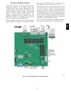
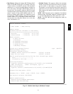
Economizer c ontrols —
Outdoor Air Enthalpy Control (PNO 33CSENTHSW) --
The enthalpy control (33CSENTHSW) is available as a
field-- installed accessory to be used with the EconoMi$er2
dampe r syst em. T he outdoor air enthalpy sensor is part of
the enthalpy control. (The separate field--inst alled
accessory return air enthalpy sensor (33CSENTSEN) is
required for differential enthalpy cont rol. See “Return Air
Enthalpy Sensor” for details.)
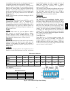
Loca te the enthalpy control in the economizer next to the
Actuator Motor. Locate two GRA leads in the factory
harness and connect the gray lead labeled “ESL” to the
terminal labeled “LOW”. See Fig. 56. Connect the
entha lpy control power input terminals to economizer
act uator power leads RED (connect to 24V) and BLK
(connect to GND).
7
ESL
CTB
ECON
LOW
GND
24V
Enthalpy
Switch
GRA
BLK
RED
Factory Wiring Harness
ECONO
MOTOR
C09026
Fig. 56 -- En thalpy Switch (33CSENTHSW) Connections
The outdoor enthalpy change over setpoi nt is set at the
enthalpy controller.
The enthalpy control receives the outdoor air enthalpy
from the outdoor air enthalpy sensor and provides a dry
conta ct switch input to the RTU--MP controller. A closed
contact indicates that outside air is preferred to the return
air. An open contact indicates that the economi zer should
remain at minimum position.
548J