


39
Differential Ent halpy Control — Different ial enthalpy
control is provided by sensing and comparing the outside
air and return air enthal py conditions. Install the outdoor
air enthalpy control as described above. Add and install a
return a ir enthalpy sensor.
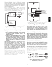
Return Air Enthalpy Sensor — Mount the ret urn--ai r
entha lpy sensor (33CSENTSEN) in the return--air section
of the ecomomizer. The return air sensor is wired to the
entha lpy controller (33CSENTHSW). See Fig. 57.
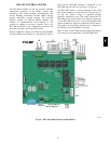
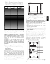
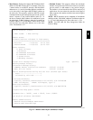
ESL
LOW
GND
24V
GRA
BLK
RED
ECONO
MOTOR
– 4-20
Main
+ VDC
Out
– 4-20 Main
Out
+ 24-36
VDC In
C09027
Fig. 57 -- Outsid e and Return Air Enthalpy S ensor
Wiring
To wire the return air enthalpy sensor, perform the
following:
1. Use a 2--conductor, 18 or 20 AWG, twisted pair cable
to connect the return air enthalpy sensor to the
enthalpy controller.
2. Connect the field--supplied RED wire to (+) spade
connec tor on the re turn air enthalpy sensor and the
(+) terminal on the enthalpy controller. Connect the
BLK wire to (--) spade connector on the return air
entha lpy sensor and the (--) termina l on the enthalpy
controller.
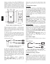
Indoor Air Quality (CO
2
sensor) — The indoor air quality
sensor accessory monitors space carbon dioxide (CO
2
)
levels. This information is used to monitor IAQ levels.
Several types of sensors are available, for wall mounting
in the space or in return duct, with and without LCD
display, and in combination with space temperature
sensors. Sensors use infrared technology to measure the
levels of CO
2
present in the space air.
The CO
2
sensors are all factory set for a range of 0 to
2000 ppm and a linear mA output of 4 to 20. Refer to the
instructions supplied with the CO
2
sensor for electrical
requirements and terminal locati ons. See Fig. 58 for
typical CO
2
sensor wiring schematic.
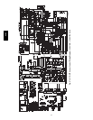
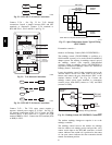
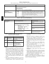
8
7
6
5
4
32
1
2
1
HG
24 VAC
OR
24 VDC
NC
ALARM
RELAY
CONTACTS
COM
NO
}
0-10VDC
SIG COM (J4-6)
4-20mA (J4-5)
+
+
-
+
-
C07134
Fig. 58 -- Indoor/Outdoor Air Quality (CO
2
)Sensor
(33ZCSENCO
2
) -- Typical Wiring Diagram
To accurately monitor the quality of the air in the
conditioned air space, locate the sensor near a return--air
grille (if present) so it senses the concentration of CO
2
leaving the space. The sensor should be mounted in a
location to avoid direct breath contact.
Do not mount the IAQ sensor in drafty areas such as near
supply ducts, open windows, fans, or over heat sources.
Allow at least 3 ft (0.9 m) between the sensor and any
corner. Avoid mounting the sensor where it is influenced
by the supply air; the sensor gi ves inaccurate readings if
the supply air is blown dir ectly onto the sensor or if the
supply air does not have a chance to mix wit h the room air
before i t is drawn into the return airstream.
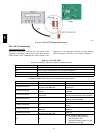
Wiring the Indoor Air Quality Sensor —
For each sensor, use two 2--conductor 18 AWG (American
Wire Gage) twisted--pair cables (unshielded) to connect
the separate isolated 24 vac power source to the sensor
and to connect the sensor to the control board te rminals.
To connect the sensor to the control, identify the positive
(4 to 20 mA) and ground (SIG COM) termina ls on the
sensor. See Fig. 58. Connect the 4--20 mA terminal to
RTU-- MP J4 -- 2 and connect the SIG COM terminal to
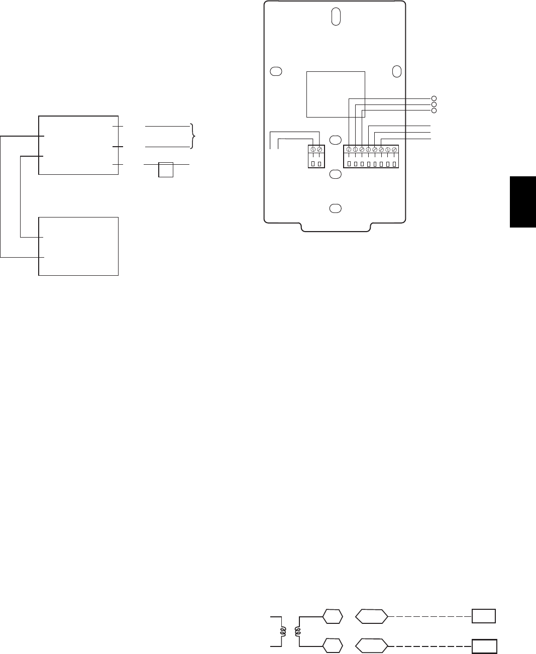
RTU--MP J4--3. See Fig. 59.
SEN
COM
J4-2
J4-3
IAQ Sensor
24 VAC
C08462
Fig. 59 -- RTU--MP / Indoor CO
2
Sensor
(33Z CSENCO2) Connectio ns
548J