


19
CONVENIENCE OUTLETS
ELECTRICAL OPERATION HAZARD
Failure to follow this warning c ould result in personal
injury or death.
Units with conveni ence outl et circuits may use
multiple disconnects. Check convenience outlet for
power status before opening unit for service. Locate
its disconnect switch, if appropriate, and open it.
Tag--out this switch, if necessary.
!
WARNING
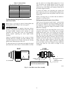
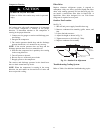
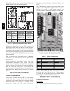
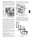
Tw o types of c onvenience out lets ar e offered on 548J
models: Non--powered and unit--powered. Both types
provide a 125--volt GFCI (ground--fa ult circuit--in terrupter)
duplex receptacle rated at 15--A behind a hinged w aterproof
access cover, located on the en d panel of the u nit. See
Fig. 22.
Convenience
Outlet
GFCI
Pwd-CO
Fuse
Switch
Pwd-CO
Transformer
Control Box
Access Panel
C08128
Fig. 22 -- Convenience Outlet Location
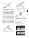
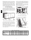
Installing Weatherproof Cover –
A weathe rproof while-in-use cover f or the
factory-installed convenience outlets is now required by
UL standards. This cover ca nnot be factory-mounted due
its depth; it must be installed at unit installation. For
shipment, the convenience outlet is covered with a blank
cover plate.
The weatherproof cover kit is shipped in the unit’s control
box. The kit includes the hinged cover, a backing plate
and gasket.
DISCONNECT ALL POWER TO UNIT AND
CONVENIENCE OUTLET.
Remove the blank cover plate at the convenie nce outlet;
discard the blank cover.
Loosen the two screws at the GFCI duplex outlet, until
approximately
1
/
2
-in (13 mm) under screw heads are
exposed. Press the gasket over the screw heads. Slip the
backi ng plate over the screw heads at the keyhole slots
and align with the gasket; tighten the two screws until
snug (do not over-tighten).
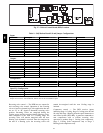
Mount the weatherproof cover to the backing plate as
shown in Fig. 23. Remove two slot fillers in the bottom of
the cover to permit service tool cords to exit the cover.
Check for full closing and latching.
RECEPTACLE
NOT INCLUDED
COVER – WHILE-IN-USE
WEATHERPROOF
BASE PLATE FOR
GFCI RECEPTACLE
C09022
Fig. 23 -- Weatherproof Cover Installation
Non --powered type: This type requires the fiel d
installation of a general--purpose 125--volt 15--A circuit
powered from a source elsewhere in the building. Observe
national and local codes when selecting wire size, fuse or
breake r requirements and disconnec t switch size and
loca tion. Route 125--v power supply conductors into the
bottom of the utility box containing the duplex receptacle.
Unit--po wered type: A unit--mounted transformer is
fact ory--installed to stepdown the main powe r supply
voltage to the unit to 115--v at the duplex receptacle. This
option also includes a manual switch with fuse, located in
a utility box and mounted on a bracket behind the
convenience outlet; access is through the unit’s c ontrol
box access panel. See Fig. 22.
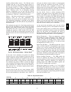
The primary leads to the convenience outlet transformer
are not factory -- connected. Selection of primary power
source is a customer--option. If local codes permit, the
transformer primary leads can be connected at the
line--side te rminals on the unit--mounted non--fused
disconnec t or HACR breaker switch; this will provide
service power to the unit when the unit disconnect switch
or HACR switch is open. Other connection methods will
result i n the convenience outlet circuit being de--energized
when the unit disconnect or HACR switch is open. See
Fig. 24.
Duty Cycle: the unit--powered convenience outle t has a
duty cycle limitation. The transformer is intended to
provide power on an intermittent basis for service tools,
lamps, etc; it is not intended to provide 15--amps loading
for continuous duty loads (such as electric heate rs for
overnight use). Observe a 50% limit on circuit loading
above 8--amps (i.e., limit loads exceeding 8--amps to 30
minutes of operation every hour).
Test the GFCI receptacle by pressing the TEST button on
the face of the receptacle to trip and open the receptacle.
Check for proper grounding wires and power line phasing
548J