


21
Overtemperature
The com pressor has an internal protector to protect it
agai nst excessively high discharge gas temper atures.
High Pressure
Switch
The system is provided with a high pressure switch
mounted on t he discharge line. The switch is
stem--mounted and brazed into the discharge tube. Trip
setting is 630 psig +/-- 10 psig (4344 +/-- 69 kPa) when
hot. Reset is automatic at 505 psig (3482 kPa).
Loss of Charge
Switch
The system is protected against a loss of charge and low
evaporator coil loading condition by a loss of charge
switch located on the liquid line and a freeze protection
thermostat on the indoor coil. The switch is
stem-- mounted. Loss of Charge Switch trip setting is
27 psig +/-- 3 psig (186 +/-- 21 kPa). Reset is automatic at
44 +/-- 3 psig (303 +/-- 21 kPa).
Freeze Protection Thermostat trip setting is 30_F+/--5_F
(-- 1_C+/--3_C). Reset is automatic at 45_F+/--5_F(7_C
+/--3_C).
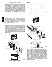
Supply (Indoor) Fan Mot or Protection
Disconnect and lockout power when servi cing fan motor.
2.9 and 3.7 bhp motors are equipped with an
overtemperature or protection device. The type of device
depends on the motor size. See Table 8.
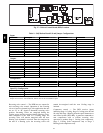
Table 8 – Overload Device per Motor Size
Motor Size ( bhp) Overload Device Reset
1.7 Internal Linebreak Automatic
2.4 Internal Linebreak Automatic
2.9 Thermix Automatic
3.7 Thermix Automatic
4.7
External
(Cir cuit Breaker)
Manual
The High Static option supply fan motor is equipped with
a pilot--circuit Thermix combination overtemperature/
overcurre nt protecti on device. This device resets
automatically. Do not bypass this switch to correct
trouble. Determine the cause and correct it.
The Thermix device is a snap--action overtemperature
protec tion device that is imbedded in the motor windings.
It is a pilot--circuit device that is wired into the unit’s 24–v
control circuit. When this switch reaches its trip setpoint,
it opens the 24–v control circuit and causes all uni t
operation to cease. This device resets automatically when
the motor windings cool. Do not bypass this switch to
correc t trouble. Determine the cause and correct it.
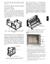
The External motor overload devic e is a
specially--calibrat ed circuit breaker that is UL recognized
as a motor overload controller. It is an overcurrent device.
When the motor current exceeds the circuit breaker
setpoint, the device opens all motor power le ads and the
motor shuts down. Reset requires a manual reset at the
overloa d swi tch. T his device (designated IFCB) is located
on the side of the supply fan housing, behind the fan
access panel.
Troubleshooting supply fan motor overl oad trips: The
supply fan used in 548J units is a forward--curved
centrifugal wheel. At a constant wheel speed, this wheel
had a characteristic that causes the fan shaft load to
DECREASE when the static pressure in the unit--duct
system increases and to INCREASE when the static
pressure in the unit--duct system decre ases (and fan
airflow rate increases). Motor overload conditions
typically develop when the unit is operated with an access
panel removed, with unfinished duct work, in an
econom izer--open mode, or a leak develops in the duct
system that all ows a bypass back to uni t return opening.
Outdoor Fan Motor Protection
The outdoor fan motor is internally protected against
overtemperature.
Control Circuit, 24-- V
The control circui t is protec ted against overcurrent
conditions by a circuit breaker mounted on control
transformer TRAN. Reset is manual.
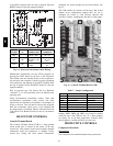
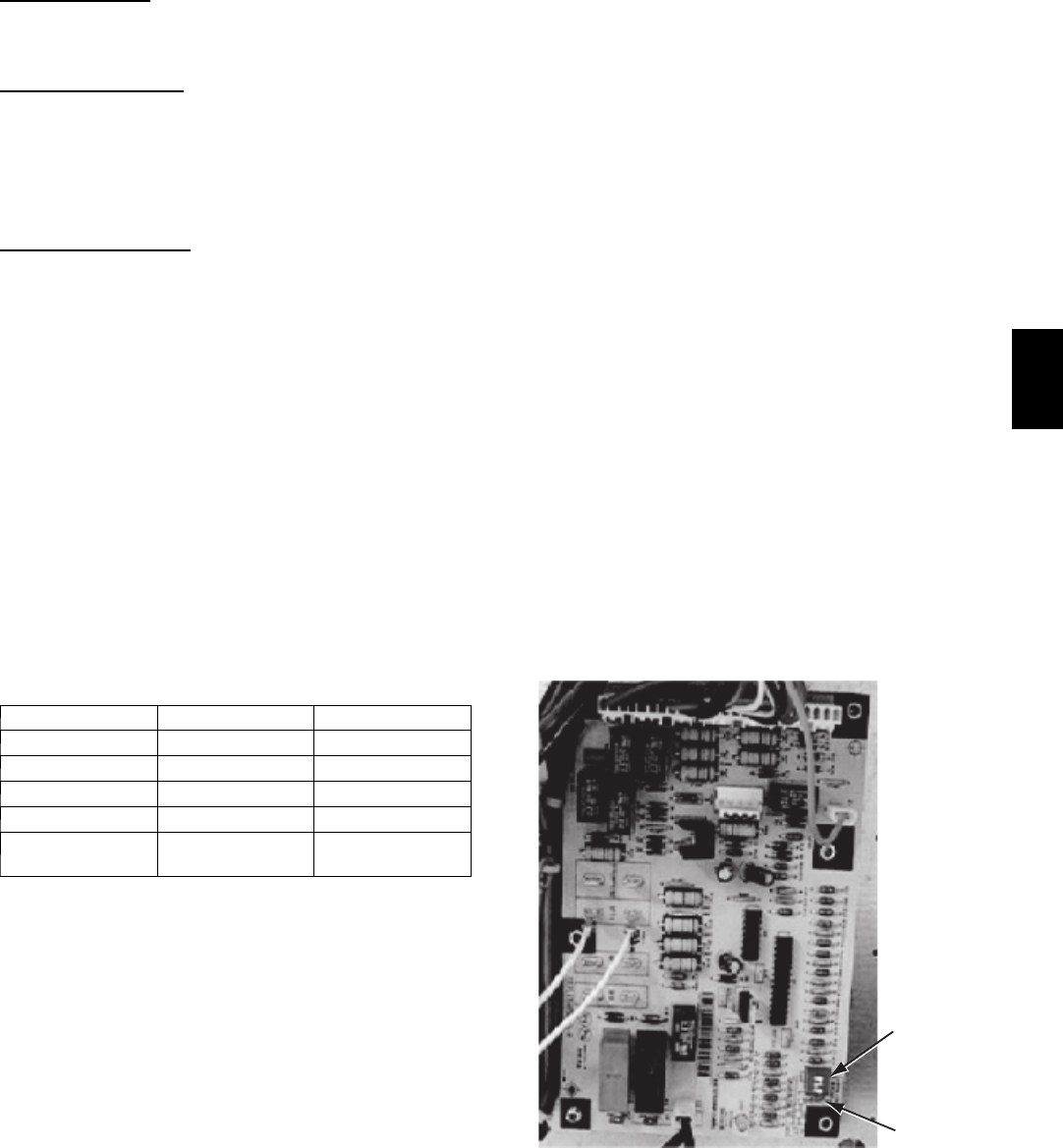
COMMERCIAL DEF ROST CONTROL
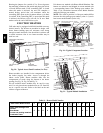
The Commercial Defrost Control Board (DFB)
coordinates thermostat demands for supply fan control, 1
or 2 stage cooling, 2 stage heating, emergency heating and
defrost control with unit operating sequences. The DFB
also provides an indoor fan off delay feature (user
selectable). See Fig. 26 for board arrangement.
DIP
Switches
Speed-Up
Jumpers
C09275
Fig. 26 -- Defrost Control Board (DFB) Arrangement
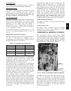
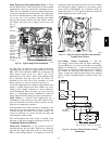
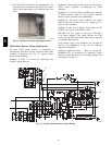
The DFB is located in the 548J’s mai n control box (see
Fig. 27). All connections are factory--made through
harnesses to the unit’s CTB, to IFC (belt--drive motor) or
to ECM (direct--drive motor), reversing valve solenoids
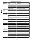
and to defrost thermostats. Refer to Table 9 for details of
DFB Inputs and Outputs. Detailed unit operating
sequence s are provided in the Operating Sequences
section starting on page 62.
548J