


31
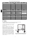
Table 13 – Detector Indicators
CONTROL OR INDICATOR DESCRIPTION
Magnetic test/reset switch Resets the sensor whe n it is in the alarm or trouble state. Activates or tests the sensor when it is in
the normal state .
Alarm LED Indicates the sensor is in the alarm state.
Trouble LED Indicates the sensor is in the trouble state.
Dirty LED Indicates the amount of environmental compensation used by the sensor
(flashing continuously = 100%)
Power LED Indicates the sensor is energized.
Detector Cleaning
Cleaning the Smoke Detector
Clean the duct smoke sensor when the Dirty LED is
flashing continuously or sooner if conditions warrant.
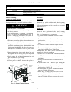
OPERATIONAL TES T HAZARD
Failure to follow this caution may result in personnel
and authorit y concern.
If the smoke detector is connected to a fire alarm
system, first notify the proper authorities that the
dete ctor is undergoing maintenance the n disable the
relevant circuit to avoid gener ating a fal se alarm .
CAUTION
!
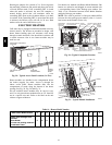
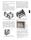
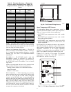
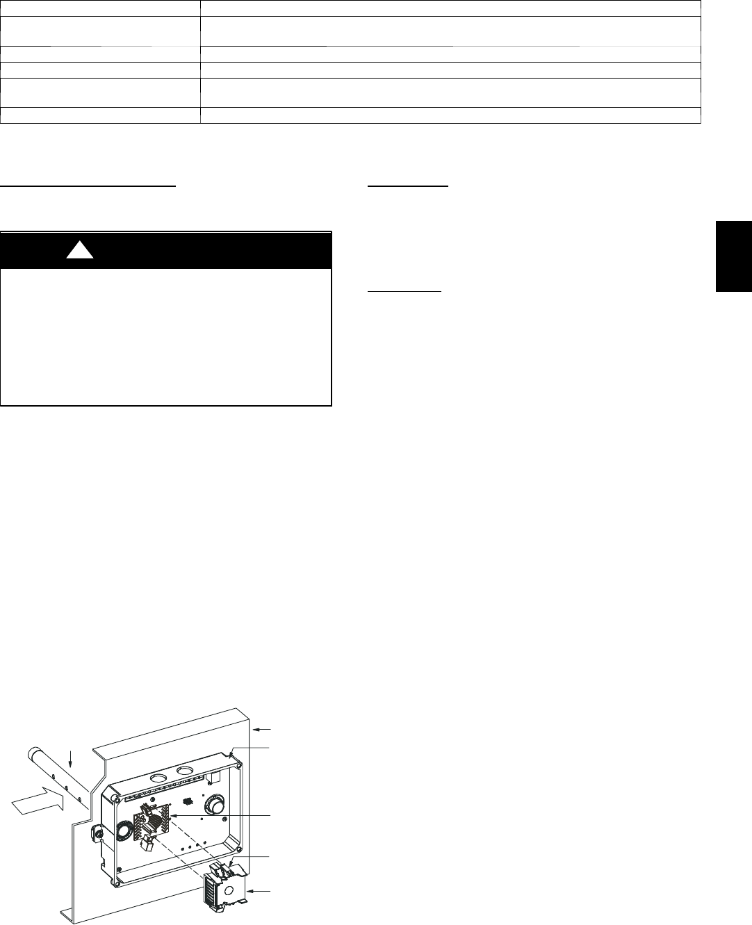
1. Disconnect power from the duct detector then remove
the sensor’s cover. (See Fig. 44.)
2. Using a vacuum cleaner, clean compressed air, or a
soft bristle brush, remove loose di rt and debris from
inside t he sensor housing and cover.
Use i sopropyl alcohol and a lint--free cloth to remove
dirt and other contaminants from the gasket on the
sensor’s cover.
3. Squeeze the retainer clips on both sides of the optic
housing then lift t he housing away from the printed
circuit board.
4. Ge ntly remove dirt and debris from around the optic
plate and inside the optic housing.
5. Replace the opti c housing and sensor cover.
6. Connect power to the duct detector then perform a
sensor alarm test.
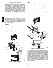
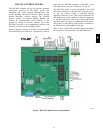
Airow
HVAC duct
Sampling
tube
Retainer
clip
Optic
plate
Optic
housing
Sensor
housing
C07305
Fig. 44 -- Sensor Cleaning Diagram
Indicators
Normal State
The smoke detector operates in the normal state in the
absence of any trouble conditions and when its sensing
chamber is free of smoke. In the normal sta te, the Power
LED on both the sensor and the cont roller are on and all
other LEDs are off.
Alarm
State
The smoke detector enters the alarm state when the
amount of smoke part iculate in the sensor’s sensing
chamber exceeds the alarm threshold value. (See
Table 13.) Upon entering the alarm state:
S The sensor’s Alarm LED and the controller’s Alarm
LED turn on.
S The contacts on the controller’s two auxiliary relays
switch positions.
S The contacts on the controller’s alarm initiation relay
close.
S The controll er’s remote alarm LED output is acti vated
(turned on).
S The controller’s high impedance multiple fan shutdown
control line is pulled to ground Trouble state.
The SuperDuct duct smoke dete ctor enters the trouble
state under t he following conditions:
S A sensor’s cover is removed and 20 minutes pass before
it is properly secured.
S A sensor’s environmental compensation limit is reached
(100% dirty).
S A wiring fault between a sensor and the controller is
detected.
An internal sensor fault is detected upon entering the
trouble state:
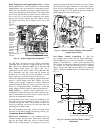
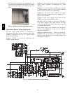
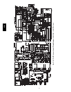
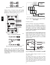
S The contacts on the controller’s supervisory relay
switch positions. (See Fig. 45.)
S If a sensor trouble, the sensor’s Trouble LED and the
controller’s Trouble LE D turn on.
S If 100% dirty, the sensor’s Dirty LED turns on and the
controller’s Trouble LE D flashes c ontinuously.
S If a wiring fault between a sensor and the controller, the
controller’s Trouble LE D turns on but not the sensor’s.
548J