


12
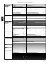
Table 5 – Defrost Mode
04A---07A and 08D---09D/Circuit 2:
Component
Status/Position
Defrost Thermostat Closed
Outdoor Fan(s) Off
Reversing Valve Energized
Check Valve A Closed
Check Valve B Open
Check Valve C Closed
Check Valve D Open
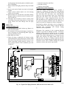
Troubleshooting Refrigerant Pressure Problems
and Check Valves
Refer to Fig. 14, on page 10, and the Cooling Mode and
Heating Mode tables (Tables 3 and 4) on page 11.
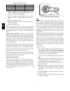
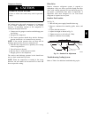
Coil Metering
Devices
The metering devices are multiple fixed–bore devices
(Acutrolt) swa ged into the horizontal outlet tubes from
the liquid header, located at the entrance to each
evapora tor coil circuit path. These are non–adjustable.
Service requires replacing the entire liquid header
assembly.
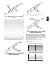
Check for possible blockage of one or more of these
metering devices by creating a low load condition on the
evapora tor--function coil and then observing the frosting
pattern on the finned portion of the coil.
To check the indoor coil, disconnect the supply fan signal
(04A--06A direct--drive fans) or contactor (IFC) coil, then
start the circuit in a Cooling Mode (jumper R to Y1 or
Y2) and observe the frosting pattern on the face of the
indoor coil. A frost pattern should develop uni formly
across the face of the indoor coil starting at each tube at
the Acutrol nipple locations.
To check the outdoor coil, disconnect the outdoor fan
motor. Start the circuit in a Heating Mode (jumper R to
W1 or W2) and observe the frost pattern on the face of the
outdoor coil.
Failure to develop frost at an outle t tube can indicate a
plugged or a missing orifice.
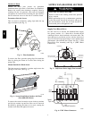
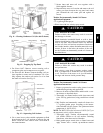
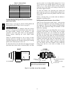
Refrigerant System Pressure Access Ports
There are two access ports in each circuit -- on the suction
tube near the compressor and on the discharge tube near
the compressor. These are brass fittings with black plastic
caps. The hose connection fittings are standard 1/4 SAE
Male Flare couplings.
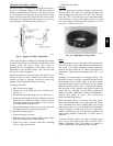
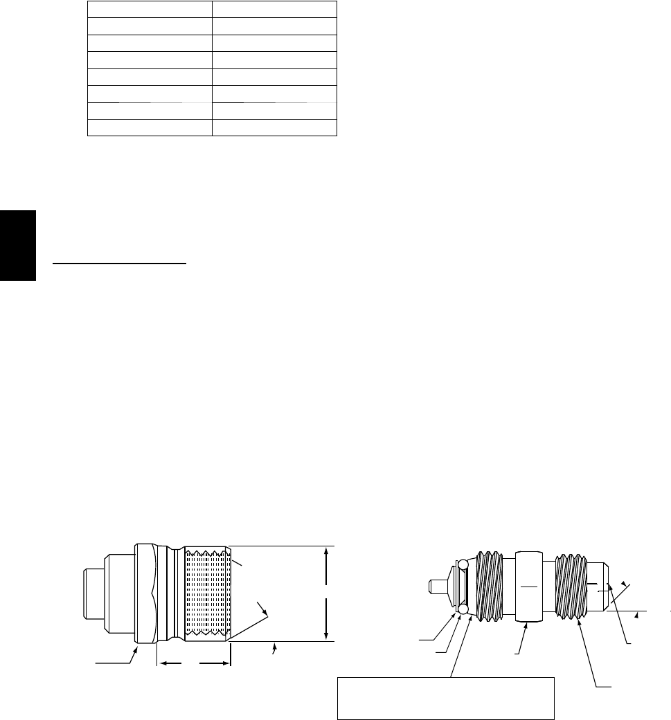
The brass fittings are two-- piece High Flow valves, with a
receptacle base brazed to the tubing and an integral
spring-- closed check valve core screwed into the base.
(See Fig. 19.) This check valve is permanently assembled
into this core body and cannot be serviced separately;
replace the entire c ore body if necessary. Service tools are
available from RCD that allow the replacement of the
chec k va lve c ore without having to recover the entire
system refrigerant charge. Apply compressor refrigerant
oil to the check valve core’s bottom o--ring. Install the
fitting body with 96 +/--10 in--lbs of torque; do not
overtighten.
1/2-20 UNF RH
30°
0.596
.47
5/8” HEX
SEAT
CORE
WASHER
DEPRESSOR PER ARI 720
+.01/-.035
FROM FACE OF BODY
7/16-20 UNF RH
O-RING
45°
1/2" HEX
This surface provides a metal to metal seal when
torqued into the seat. Appropriate handling is
required to not scratch or dent the surface.
(Part No. EC39EZ067)
C08453
Fig. 19 -- CoreMax Access Port Assembly
548J