


30
OPERATIONAL TES T HAZARD
Failure to follow this caution may result in personnel
and authorit y concern.
Changing the dirty sensor test operation will put the
detector into the alarm state and activate all automatic
alarm responses. Be fore changing dirty sensor test
operation, disconnect all auxiliary equipment from the
controller and notify the proper authorities if
connected to a fire alarm system.
CAUTION
!
Changing the Dirty Sensor Test
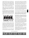
By default, sensor dirt y test results are indicated by:
S The sensor’s Dirty LED flashing.
S The controll er’s Trouble LED flashing.
S The controller’s supervision relay contacts t oggle.
The operation of a sensor’s dirty t est can be changed so
that the controller’s supervision relay is not used to
indicate test results. When two detectors are connected to
a controller, sensor dirty test operation on both sensors
must be configured to operate in the same manner.
To Configure the Dirty Sensor Test
Operation
1. Hold the test magnet where indi cated on the side of
the sensor housing until the sensor’s Alarm LED t urns
on and its Dirty LED flashes twice (approximately 60
seconds).
2. Reset the sensor by removing the t est magnet then
holding it against the sensor housing again until the
sensor’s Alarm LED turns off (approximat ely 2
seconds).
Remote Station Test
The remote station alarm test checks a test/reset station’s
ability to initiate and indicate an alarm state.
OPERATIONAL TES T HAZARD
Failure to follow this caution may result in personnel
and authorit y concern.
This test places the duct detector into the alarm state.
Unless part of the test, disconnect all auxiliary
equipment from the control ler before performing the
test. If the duct detector is connected to a fire alarm
system, notify the proper authorities before
performing the test.
CAUTION
!
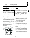
CRSDTEST001A00 Remote Alarm Test Procedure
1. Turn the key switch to the RESET/TEST position for
seven seconds.
2. Verify that the test/reset station’s Alarm LED turns
on.
3. Reset the sensor by turning the key switch to the
RESET/TEST position for two seconds.
4. Verify that the test/reset station’s Alarm LED turns
off.
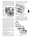
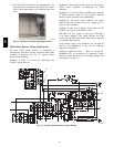
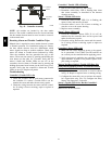
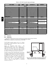
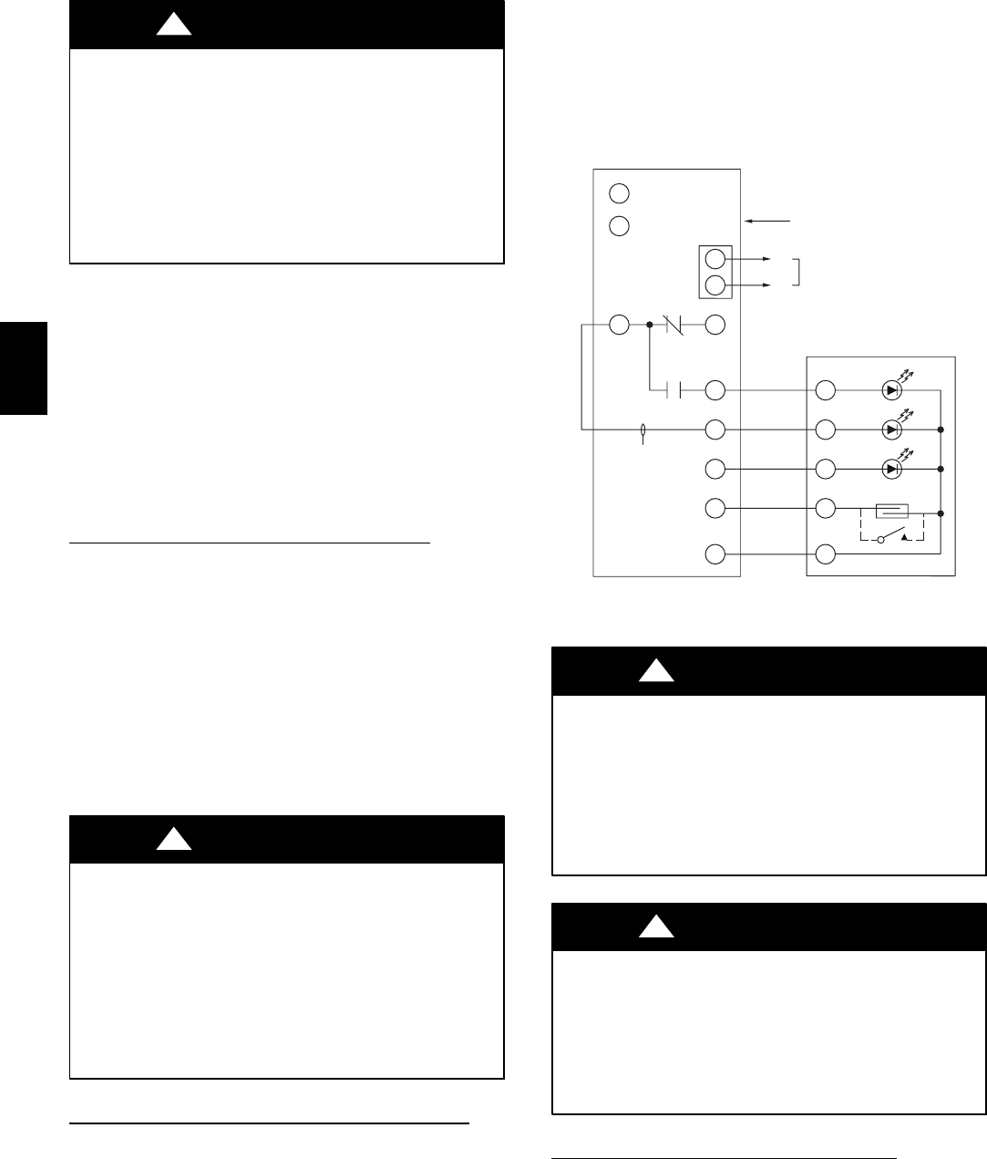
Remote Test/Reset Station Dirty Sensor Test
The test/reset station dirty sensor test checks the test/reset
station’s ability to initiate a sensor dirty test and indicate
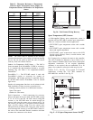
the results. It must be wired to the controller as shown in
Fig. 43 and configured to operate the controller’s
supervision relay. For more informa tion, see “Changi ng
the Dirty Sensor Test.”
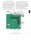
Auxiliary
equipment
Smoke Detector Controller
12
1
3
+
–
1
2
14
13
19
15
2
20
5
4
1
3
2
TB3
CRSDTEST001A00
Trouble
Power
Alarm
Reset/Test
Supervision relay
contacts [3]
Wire must be
added by installer
18 Vdc (+)
18 Vdc (
–
)
C09326
Fig. 43 -- Remote Test/Reset Station Connections
OPERATIONAL TES T HAZARD
Failure to follow this caution may result in personnel
and authorit y concern.
If the test/reset station’s key switch is left in the
RESET/TEST position for longer t han seven seconds,
the detector will automatically go into the alarm state
and activate all automatic alarm responses.
CAUTION
!
OPERATIONAL TES T HAZARD
Failure to follow this caution may result in personnel
and authorit y concern.
Holding the test magnet to the target area for longer
than seven seconds will put the detector into the alarm
state and activate all automatic alarm responses.
CAUTION
!
Dirty S ensor Test Using an CRSDTES T001A00
1. Turn the key switch to the RESET/TEST position for
two seconds.
2. Verify that the test/ r eset station’s Trouble LED
flashes.
548J