


54
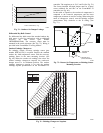
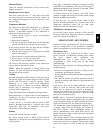
graph with the left side of the chart to determine that the
range configuration for the CO
2
sensor should be 1800
ppm. The EconoMi$er IV controller will output the 6.7
volts from the CO
2
sensor to the actuator when the CO
2
conce ntration in the spac e is at 1100 ppm. The DCV
setpoint may be left at 2 volts since the CO
2
sensor
voltage wi ll be ignored by the EconoMi$er IV controller
until it rises above the 3.6 volt setting of the minimum
position potentiometer.
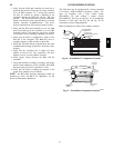
Once the fully occupied damper position has been
determined, set the maximum damper demand control
ventilation potentiometer to this position. Do not set to the
maximum position as this can result in over-ventilation to
the space and potential high humidity levels.
CO
2
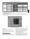
Sensor Configuration
The CO
2
sensor has preset st andard voltage settings that
can be selected anytime after the sensor is powered up.
(See Table 23.)
Use setting 1 or 2 for Bryant equipment. (See Table 23.)
1. Pre ss Clear and Mode buttons. Hold at least 5 seconds
until the sensor enters the Edit mode.
2. Press Mode twice. The STDSET Menu will appear.
3. Use the Up/Down button to select the preset number.
(See Table 23.)
4. Press Enter to lock in the selection.
5. Press Mode to exit and resume normal operation.
The custom settings of the CO
2
sensor can be changed
anytime after the sensor is energized. Follow the steps
below to change the non-standard settings:
1. Pre ss Clear and Mode buttons. Hold at least 5 seconds
until the sensor enters the Edit mode.
2. Press Mode twice. The STDSET Menu will appear.
3. Use the Up/Down button to toggle to the NONSTD
menu and press Enter.
4. Use the Up/Down button to toggle through each of
the nine variables, starting with Altitude, until the
desired setting is reached.
5. Pre ss Mode to move through the var iables.
6. Press Enter to lock in the selection, then press Mode
to continue to the next variable.
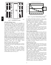
Dehumidification of Fresh Air with DCV (Demand
Controlled Ventilation) Control
If normal rooftop heating and cooling operation is not
adequa te for the outdoor humidit y level, an energy
recove ry unit and/or a dehumidification option should be
considered.
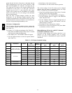
Table 23 – CO2 Sensor Standard Settings
SETTING EQUIPMENT OUTPUT
VENTILATION
RATE
(cfm/Person)
ANALOG
OUTPUT
CO
2
CONTROL RANGE
(ppm)
OPTIONAL
RELAY SETPOINT
(ppm)
RELAY
HYSTERESIS
(ppm)
1
Interface w/Standard
Building Control System
Proportional Any
0-10V
4-20 mA
0-2000 1000 50
2
Proportional Any
2-10V
7-20 mA
0-2000 1000 50
3
Exponential Any
0-10V
4-20 mA
0-2000 1100 50
4
Economizer
Proportional 15
0-10V
4-20 mA
0-1100 1100 50
5
Proportional 20
0-10V
4-20 mA
0- 900 900 50
6
Exponential 15
0-10V
4-20 mA
0-1100 1100 50
7
Exponential 20
0-10V
4-20 mA
0- 900 900 50
8
Health & Safety Proportional —
0-10V
4-20 mA
0-9999 5000 500
9
Parking/Air Intakes/
Loading Docks
Proportional —
0-10V
4-20 mA
0-2000 700 50
LEGEND: ppm— Parts Per Million
548J