


10
Avoid s pr ayin g in horizo ntal pattern to minimize p ot en-
tial for fin damage.
7. Ensure cle aner thoroughly penetrate s deep into finned
areas.
8. Interior and exterior finned areas must be thoroughly
cleaned.
9. Finned surfaces should remain wet with cleaning
solution for 10 minutes.
10. Ensure surfaces are not allowed to dry before rinsing.
Reapply cleaner as needed to ensure 10-- minute satur-
ation is achieved.
11. Thoroghly rinse all surfaces with low velocity clean
water using downward rinsing motion of water spray
nozzle. Protect fins from damage from the spray
nozzle.
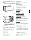
Indoor Coil
Cleaning the Indoor Coil
1. Turn unit power off. Install lockout tag. Remove in-
door coil access panel.
2. If economizer or two--position damper is installed, re-
move economizer by disconnecting Molex plug and
removing mount ing scre ws.
3. Slide filters out of unit.
4. Clean coil using a commercial coil cleaner or dish-
washer detergent in a pressurized spray canister. Wash
both sides of coil and flush with clean water. For best
results, back--flush toward return -- air section to re-
move forei gn material. Flush condensate pan after
completion.
5. Reinstall economizer and filters.
6. Reconnect wiring.
7. Replace access panels.
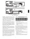
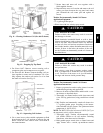
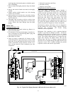
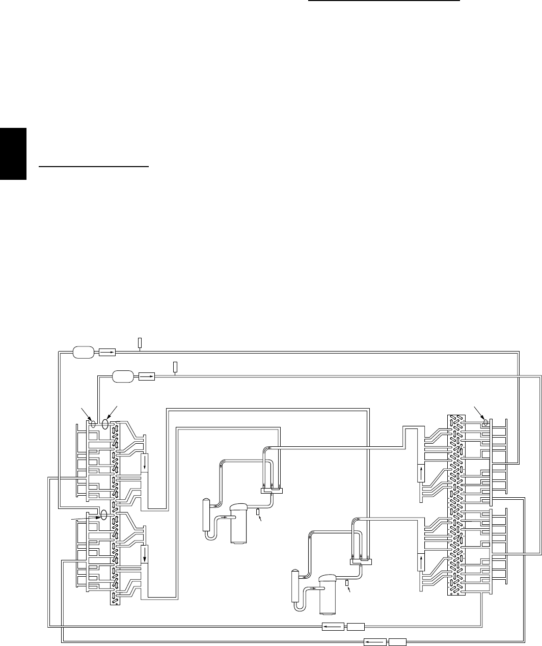
Refrigeration System
Components
Eac h heat pump refrigeration system includes a
compressor, accumulator, reversing valve, dual-- function
outdoor coil wi th vapor header check valve, cooling liquid
line with filter drier and check valve, dual--function
indoor coil with vapor header check valve, and heating
liquid line with check valve and strainer. Unit sizes
04A--07A have a single compressor--circuit; unit sizes
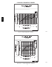
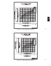
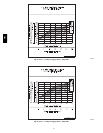
08D and 09D have two compressor--circuits. See Fig. 14
for typical unit piping schematic (unit size 09D (4--row
indoor coi l) with two compressor --circuits is depicted).
Dual--function outdoor and indoor coils are designed to
provide parallel coil circuits during evaporator--function
operation and converging coil circuits during
condenser--functi on operation.
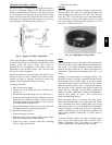
Refrigerant flow metering in the evaporator--function
sequence is provided by multiple Acutrols – fixed-- bore
metering devices that are located in the tee nipples
between the liquid header and the entrance to each coil
circuit. The Acutrol metering device is swaged into the
nipple tube betwe en the liquid header end and the
side--port tube. See Fig. 15. During evaporator--function
operation, flow is straight through the nipple and into each
evapora tor circuit. Flow continues through the parallel
evapora tor circuits and into the vapor header.
COMPRESSOR
ACCUMULATOR
HPS
COMPRESSOR
ACCUMULATOR
HPS
Filter
Drier
2B
1B
LPS/LOC
Acutrol
DFT 1
Cooling Liquid Lines
DFT 2
2A
1A
1D
2D
Outdoor Coil
Indoor Coil
Comp 2
Comp 1
2C
1C
Strainer
Heating Mode Liquid Lines
Acutrol
C09228
Fig. 14 -- Typical Unit Piping Schematic (09D unit with 4--row indoor coil)
548J