


37
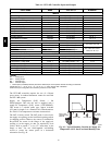
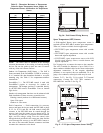
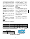
Table 15 – Thermistor Resistance vs Temperature
Values for Space Temperatur e Sensor, Supply Air
Temperature Sensor, and Outdoor Air Temperature
Sensor
TEMP
(C)
TEMP
(F)
RESISTANCE
(Ohms)
--- 40 --- 40 335,651
--- 35 --- 31 242,195
--- 30 --- 22 176,683
--- 25 --- 13 130,243
--- 20 --- 4 96,974
--- 15 5 72,895
--- 10 14 55,298
--- 5 23 42,315
0 32 32,651
5 41 25,395
10 50 19,903
15 59 15,714
20 68 12,494
25 77 10,000
30 86 8,056
35 95 6,530
40 104 5,325
45 113 4,367
50 122 3,601
55 131 2,985
60 140 2,487
65 149 2,082
70 158 1,752
NOTE: The sensor must be mounted in the discharge
airstre am downstream of the cooling coil and any heating
devic es. Be sure the probe tip does not come in contact
with any of the unit’s heater surfaces.
Outdoor Air Temperatu re (OAT) Sensor — The O AT is
factory--mounted in the EconoMi$er 2 (FI OP or accesso ry).
It is a nominal 10k ohm thermistor attached to an eyelet
mounting r ing. See T able 15 for temperature--resistan ce
characteristic.
EconoMi$e r 2 — T he RTU--MP control is used with
EconoMi$er2 (option or accessory) for outdoor air
management. The damper position is controlled directly
by the RTU--MP c ontrol; EconoMi$er 2 has no internal
logic device.
Outdoor air management functi ons can be enhanced with
field--installation of these accessory control devices:
Enthalpy control ( outdoor air or differential sensors)
Space CO
2
sensor
Outdoor air CO
2
sensor
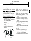
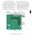
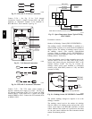
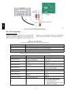
Field Connections — Field connections for accessory
sensors and input devices are made the RTU--MP, at plugs
J1, J2, J4, J5, J11 and J20. All field control wiring that
connec ts to the RTU--MP must be rout ed through the
raceway built into the corner post as shown in Fig. 50.
The raceway provides the UL required clearance between
high-- and low--voltage wiri ng. Pass the control wires
through the hole provided in the corner post, then feed the
wires thorough the raceway to the RTU--MP. Connect to
the wires to the removable Phoenix connectors and then
reconne ct the connect ors to the board.
RACEWAY
HOLE IN END PANEL (HIDDEN)
C08027
Fig. 50 -- Field Control Wiring Raceway
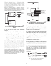
Space Temperature (SPT) Sensors
A field-- supplied Bryant space temperature sensor is
required with the RTU--MP to monitor space temperature.
There are 3 sensors available for this application:
S 33ZCT55SPT, space temperature sensor with override
button
S 33ZCT56SPT, space temperature sensor with override
button and set point adjustment
S 33ZCT 59SPT, spac e tempe rature sensor with LCD
(liquid crysta l display) screen, override butt on, and
setpoint adjustment
Use 20 gauge wire to connect the sensor to the controller.
The wire is suitable for distances of up to 500 ft. Use a
three--conductor shielded cable for the sensor and setpoint
adjustment connections. If the setpoint adjustment
(slidebar) is not required, the n an unshielded, 18 or 20
gauge, two--conductor, t wisted pair cable may be used.
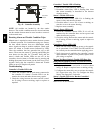
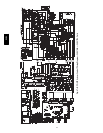
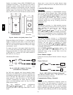
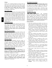
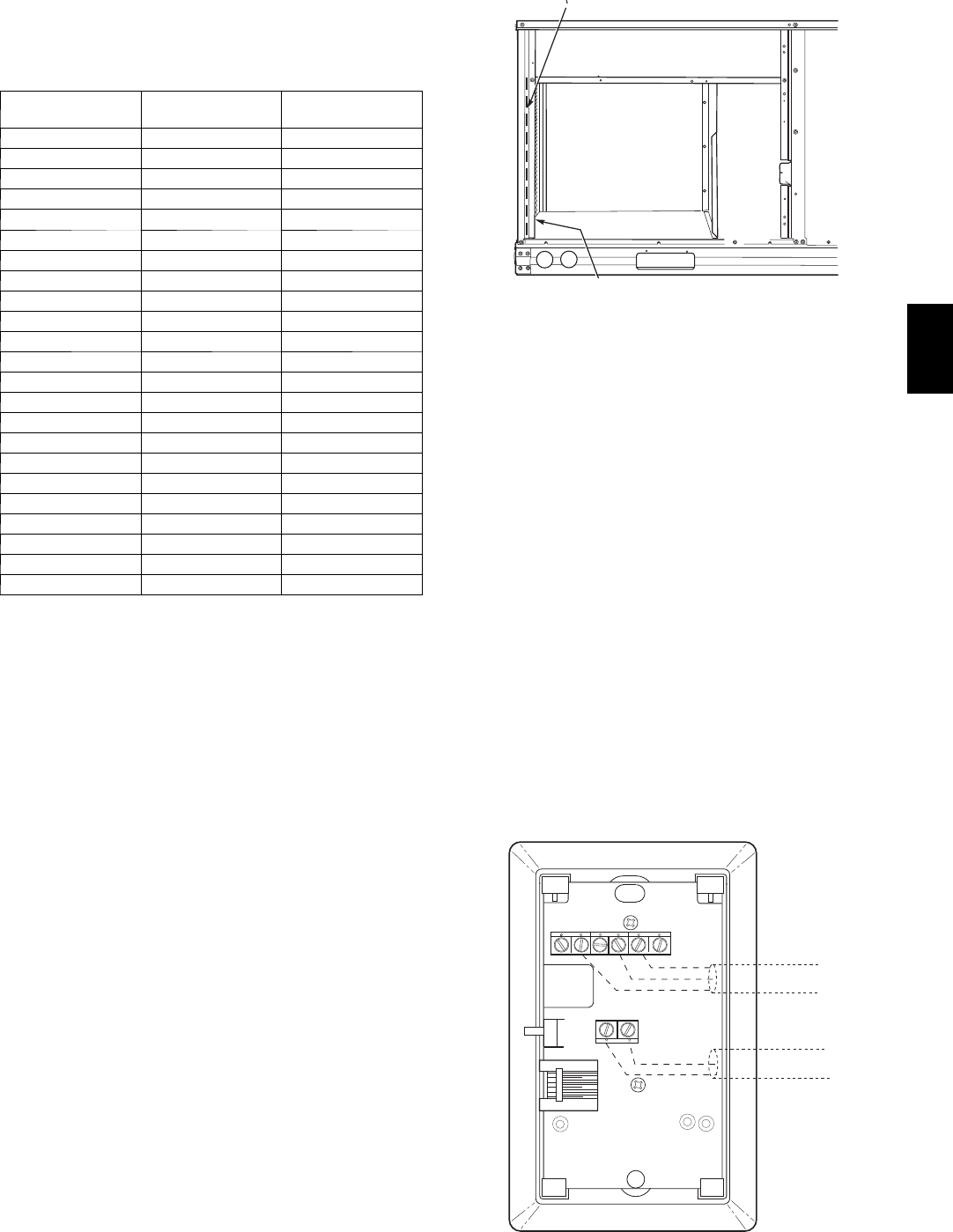
Connect T--55 -- See Fig. 51 for typical T--55 internal
connec tions. Connect the T--55 SEN terminals t o
RTU--MP J20--1 and J20--2. See Fig. 52.
2
3
45
61
SW1
SEN
BRN (GND)
BLU (SPT)
RED(+)
WHT(GND)
BLK(-)
CCN COM
SENSOR WIRING
C08201
Fig. 51 -- T--55 Space Temperatur e Sensor Wiring
548J