


6
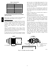
Table 2 – Motor Test Volts
Unit Voltage Motor Voltage Min---Max Volts
208/230 230 190---250
460 230 210---250
575 460 420---500
5. Apply a jumper at unit cont rol terminals R to G to
initiate a demand for motor operation. Check for 24--v
output a t defrost board terminal IFO.
6. Check for proper control signal voltage at motor
signal leads VIO and BRN. Signal should be 22 to
28--v.
7. Disc onnect unit main power.
8. Reconnect motor power and control signal leads at
the motor terminals.
9. Restore unit main power.
Motor should start and run. If it does not, remove the
motor assembly. Replace with same motor part number;
do not substitute with an alternate design as torque/speed
programming will not be same as on original factory
motor.
Replacing the ECM Motor – Before removing the ECM
belly--band mounting ring, measure the dist ance between
the base of the motor shaft and the edge of the mounting
ring. Remove the motor mounting band a nd transfer to the
replacement motor. Position the mounting band at
distance measured in first step. Snug t he mounting bolt
but do not tighten yet.
Insert the m otor shaft into the fan wheel hub. Then secure
the three motor mount arms to the support cushions.
Torque t he arm mounti ng screws to 60 in--lbs (6.8 N--m).
Cente r the fan wheel in the fan housing. Torque the fan
wheel hub setscrew to 120 in--lbs (13.6 N--m).
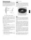
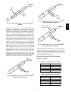
Ensure the motor terminals are located at a position below
the 3 o’clock position (see Fig. 5). Tighten the motor
belly--band bolt to 80 in--lbs (9.0 N--m).
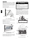
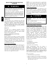
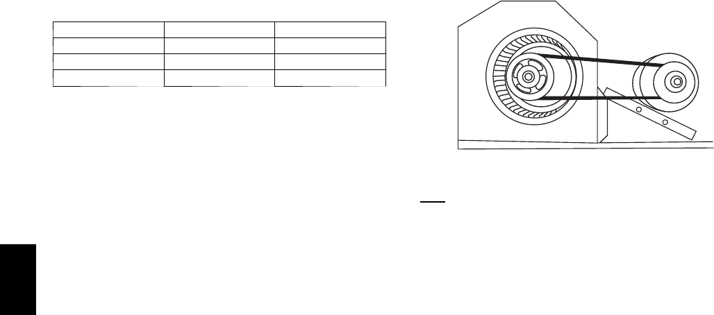
Supply Fan (Belt--Drive)
The belt--drive supply fan system consists of a
forward--curved c entrifugal blower wheel on a solid shaft
with two concentric type bearings, one on each side of the
blower housing. A fi xed--pitch driven pulley is attached to
the fan shaft and an adjustable--pitch driver pulley is on
the motor. The pulleys are connected using a “V” type
belt. (See Fig. 8.)
C07087
Fig. 8 -- Belt Drive Motor Mounting
Belt
Check the belt condition and tension quarterly. Inspect the
belt for signs of cracking, frayi ng or glazing along the
inside surfaces. Check belt tension by using a spring--force
tool (such as Browning’s Part Number “Belt Tension
Checke r” or equivalent tool); tension should be 6--lbs at a
5
/
8
--in. deflection when measured at the centerline of the
belt span. This point is at the center of the belt when
mea suring the distance between the motor shaft and the
blower shaft.
NOTE: Wit hout the spring--tension tool, place a straight
edge across the belt surface at t he pulleys, then deflect the
belt at mid--span using one finger to a
1
/
2
--in. deflection.
Adjust belt tension by loosening the motor mounting plate
front bolts and rear bolt and sliding t he plate toward the
fan (to reduce tension) or away from fan (to increase
tension). Ensure the blower shaft and the motor shaft are
parallel to each other (pulleys aligned). Tighten all bolts
when finished.
To replace the belt:
1. Use a belt with same section type or similar size. Do
not substitute a “FHP” type belt. When installing the
new belt, do not use a tool (screwdriver or pry--bar) to
force the belt over the pulley flanges, this wil l stress
the belt and cause a reduction in belt life.
2. Loosen the motor mounting plate front bolts and rear
bolts.
3. Push the motor and its mounting plate towards the
blower housing as close as possible to reduce the ce n-
ter distance between fan shaft and motor shaft.
4. Remove the belt by ge ntly lifting the old belt over
one of the pulleys.
5. Install the new belt by gently sliding the belt over
both pulleys and then sliding the motor and plate
away from the fan housing until proper tension is
achi eved.
6. Check th e a lignmen t of the pulleys, adjus t i f necess ary.
7. Tighten all bolts.
8. Check the tension after a few hours of runtime and
re--adjust as required.
548J