


3
UNIT ARRANGEMENT AND ACCESS
General
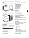
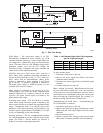
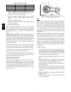
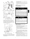
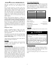
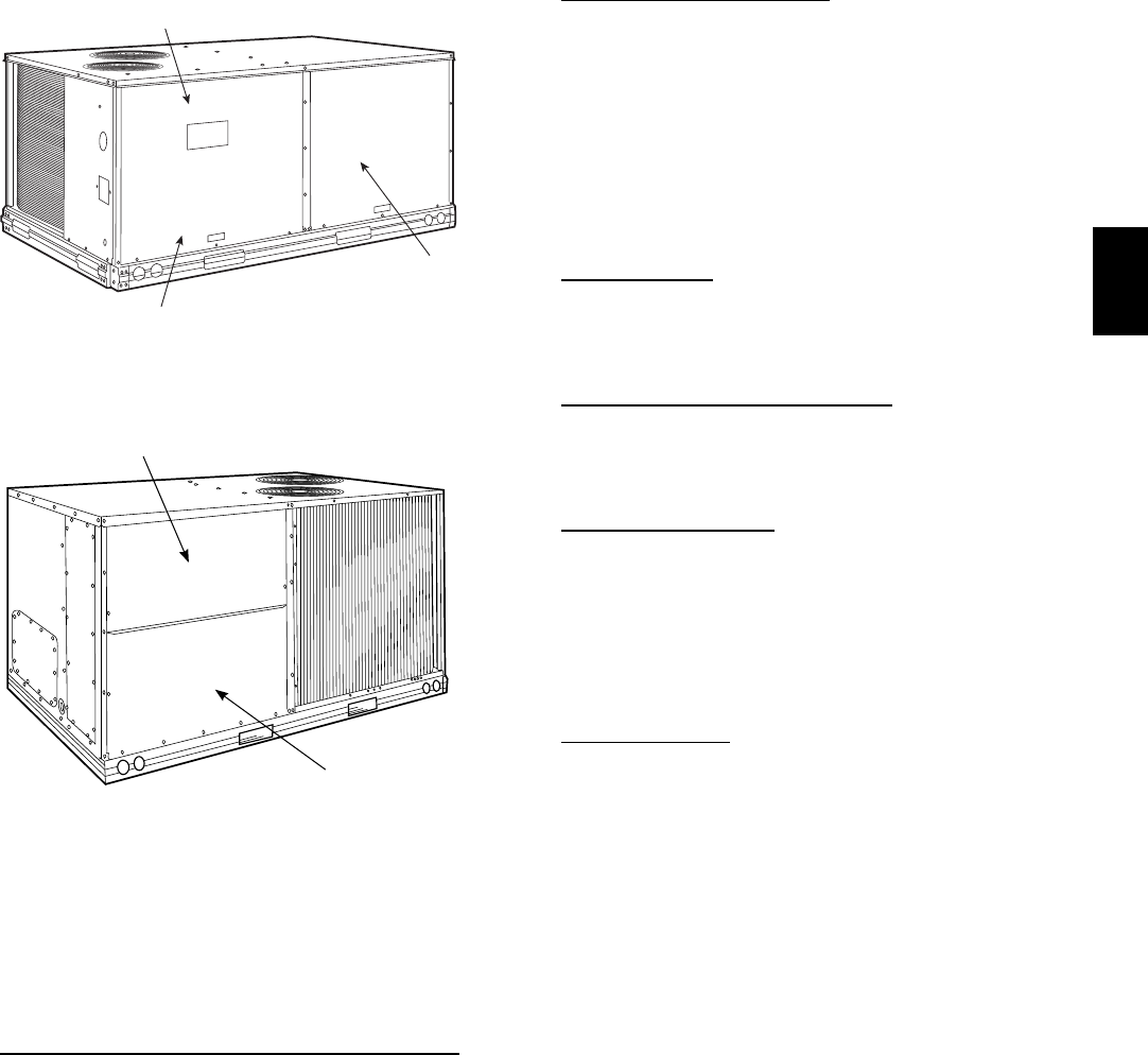
Fig. 1 and Fig. 2 show general unit arrangement and
access locations.
INDOOR BLOWER
ACCESS
CONTROL BOX
COMPRESSORS
(D08-09 only)
C09190
Fig. 1 -- Typical Access Panel Location (Front)
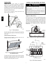
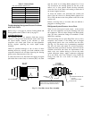
FILTER ACCESS PANEL
INDOOR COIL ACCESS PANEL
C08449
Fig. 2 -- Typical Access Panel Locations (Rear)
Routine Maintenance
These items should be part of a routine mainte nanc e
program, to be checked every month or two, until a
specific schedule for each can be identified for this
installation:
Quarterly Ins pection (and 30 days after in itial start
)
S Return air filter replacement
S Outdoor hood inlet filters cleaned
S Belt tension checked
S Belt condition checked
S Pulley alignment checked
S Fan shaft bearing locking collar tightness checked
S Outdoor coil cleanliness checke d
S Condensa te drain checked
Seasonal Maintenance
These items should be checked at the beginning of each
season (or more often if l ocal conditions and usage
patterns dictate):
Air Conditioning/Heat
Pump
S Outdoor fan motor mounting bolts tightness
S Compressor mounting bolts
S Outdoor fan blade positioning
S Control box cleanliness and wiring condition
S Wire terminal tightness
S Refrigerant charge level
S Indoor coil cleaning
S Supply blower m otor amperage
Electric
Heating
S Power wire connec tions
S Fuses ready
S Manual--reset limit switch is closed
Economizer or Outside Air
Damper
S Inlet filters condition
S Check damper travel (economizer)
S Check gear and dampers for debris and dirt
Air Filters and Scr
eens
Each unit is equipped with return air filters. If the unit has
an economizer, it will also have an outside air screen. If a
manua l outside ai r damper is added, an inlet air screen
will also be present.
Each of these filters and screens will need to be
periodically replaced or cleaned.
Return Air
Filters
Return air filters are disposable fiberglass media type.
Access to the filters is through the small lift--out panel
loca ted on the rear side of the unit, above t he
evaporator/return air access panel. (See Fig. 1.)
To remove the filters:
1. Gra sp the bottom flange of the upper panel.
2. Lift up and swing the bottom out until the panel dis-
engage s and pulls out.
3. Reach inside and extract the filters from the filter
rack.
4. Replace these filters as required with similar replace-
ment filters of same size.
To re--install the access panel:
1. Slide the top of the panel up under the unit top panel.
2. Slide the bottom into the side channels.
3. Push the bottom flange down until it contacts the top
of the lower panel (or ec onomizer top).
IMPORTANT: DO NOT OPERATE THE UNIT
WITHOUT THESE FILTERS!
548J