


25
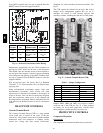
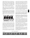
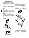
Single Po int Bo xes and Supplementa ry Fuses — When
the unit MOCP device value exceeds 60--A, unit--mounted
supplementary fuses are required for each heater circuit.
These fuses are included in accessory Single Point Boxes,
with power distribution and fuse blocks. The single point
box will be installed directly under the unit control box,
just to the left of the partition separating the indoor
section (with el ectric heaters) from the outdoor section.
The Single Point Box has a hinged access cover. See
Fig. 32.
A
L
LIE
D
P
A
M
O
DE
L
N
O
.
ERI
A
L
N
O.
C
O
R
P
.
11
13
21
23
O
D
2
2
.
2
3
1
2
3
ISTED
AIR
NDITIONING
UIP
ACCESS
346N
.
P
/ N
2-
5
6
1
0
-
4
REV
1
1
13
2
1
2
3
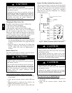
CONTROL
BOX
BUSHING
SINGLE
POINT BOX
MOUNTING
SCREWS
FOAM
BUSHING
DRIP BOOT
BRACKET
MOUNTING
SCREWS
HEATER
RELAYS
POWER
WIRES
HEATER
MOUNTING
SCREWS
C08136
Fig. 32 -- Typical Single Point Installation
On 548J units, all fuses are 60--A. Single point boxes
conta ining fuses for 208/230--V applications use UL Class
RK5 250--V fuses (Bussman FRNR 60 or Shawmut TR
60R). Single point boxes for 460--V and 575--V
applications use UL Class T 600--V fuses (Bussman JJS
60 or Shawmut A6T 60). (Note that all heaters are
qualified for use with a 60--A fuse, regardless of actual
heater ampacity, so only 60--A fuses are necessary.)
Unit heater applications not requiring supplemental fuses
require a special Single Point Box without any fuses.
Connect power supply conductors to hea ter conductors
and field--supplied base unit power tap leads (see text
below r e: “Completing Heater Installation”) inside the
empty Single Point Box using UL--approve d connectors.
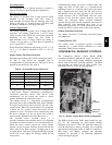
Safety Devices — Electric heater applications use a
combination of line--break/auto--reset limit switches and a
pilot--circuit/manual reset limit switch to protect the unit
against over--temperature situations.
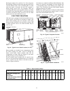
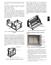
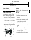
Line -- break/auto--reset limit switches are mounted on the
base plate of each heater module. See Fig. 33. These are
accessed through the indoor access panel. Remove the
switch by removi ng two screws into the base plate and
extracting the existing switch.
Pilot--circuit/manual reset limit switch is located in the
side plate of the indoor (supply) fan housing. See Fig. 30.
Completing Heater Installation
Field Power Connections — Tap conductors must be
installed between the base unit’s field power connection
lugs and the Single Point Box (with or without fuses).
Refer to unit wiring schematic. Use copper wir e only. For
connec tion using the Single Point Box less fuses, connect
the field power supply conductors to the heater power
lea ds and the field--supplied tap conductors inside the
Single Point Box. Use UL--approved pressure connectors
(field--supplied) for these splice joints.
ALLIED P
A
MODE
L
NO.
ERIAL
NO.
11
13
21
23
OD
3
1
2
3
ISTED
AIR
NDITIONING
U
I
P
ACCESS
34
6
N
.
P
/ N
2
-
5610-4
RE
V
Line-Break
Limit Switches
C08330
Fig. 33 -- Typical Location of Heater Limit Switches
(3--phase hea ter sho wn)
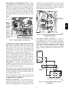
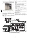
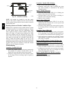
Low--Voltage Control Connections — Pull the
low--voltage control leads from the heater module(s) --
VIO and BRN (two of each if two modules are installed;
identify for Module #1) -- to the 4--pole terminal board
TB4 located on the heater bulkhead to the left of Heater
#1. Connect the VIO lead from Heater #1 to terminal
TB4--1. Connect the VIO lead from Heater #2 to terminal
TB4--2. Connect both BRN leads to terminal TB4-- 3. See
Fig. 34.
DEFROST
BOARD
ORN
BRN
Field
Connections
E-HEAT
P3-3
13
ORN BRN
VIO BRN BRN
VIO
TB4
VIO HR2
HR1
BRN
VIO BRN
Elec Htr
HR1: On Heater 1 in Position #1
HR2: On Heater 2 in Position #2 (if installed)
C09013
Fig. 34 -- Accessory Electric Heater Control
Connections
548J