


23
Auxiliary (Electric) Heat control — The 548J unit can be
equipped with one or two auxiliary electric heaters, to
provide a second stage of Heating. The DFB will energize
this Heating system for a Stage 2 Heating command
(heaters operate concurrently with both compressors in the
Stage 2 Heating cycle), for an Emergency Heating
sequence (compressors are off and only the electric
heaters are energized) and also during the Defrost cycle
(to e liminate a “cold blow” condition in the space).
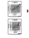
Defrost — The defrost control mode is a time/temperature
sequence. There are two time components: The
continuous run period and the test/defrost cycle period.
The temperature component is provided by the defrost
thermostat(s) (DFT1 and DFT2 (08 --09 only) mounted on
the outdoor coil.
The continuous run period is a fixed time period between
the end of the last defrost cycle (or start of the current
Heating cycle) during which no defrost will be permitted.
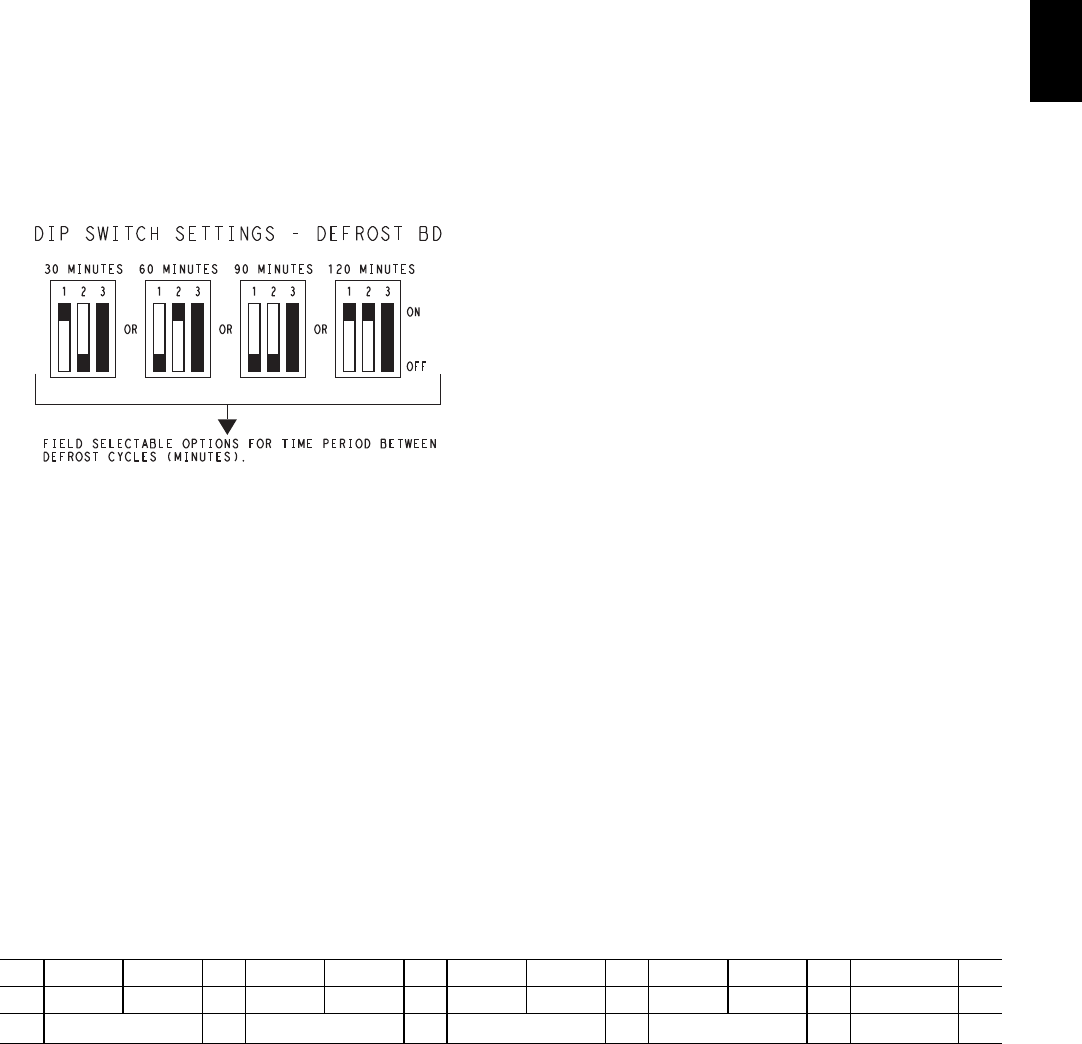
This period c an be set at 30, 60, 90 or 120 minutes by
changi ng the positi ons of DIP switches SW1 and SW2
(see Fig. 28 and Table 10). The default run periods are 30
minutes for unit sizes 04--07 and 90 minutes for unit sizes
08--09.
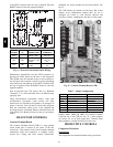
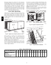
C09283
Fig. 28 -- DIP Switch Settings — Defrost Board
At the end of the continuous run period, the defrost
control will test for a need t o defrost. On unit sizes 04--07
(single compressor designs), DFT1 controls the start and
termination of the defrost cycle. If DFT1 is still open, the
defrost test/run window is c losed and the control repeats
the conti nuous run period. If DFT1 is closed, the defrost
cycle is initiated. The defrost period will end when DFT1
opens (indicating the outdoor coil has been cleared of
frost and ice) or a 10 minute elapsed period expires,
whicheve r comes first.
On unit sizes 08 and 09 (t wo circuit designs), DFT2
(loca ted on the bottom circuit of the outdoor coil) controls
the start and termination of the defrost cycle. If DFT2 is
still open, the defrost test/run window is closed and the
control repeats the continuous run period. If DFT2 is
closed, the defrost cycle is initiated in Circuit 2. The
defrost period will end when DFT2 opens (indicating the
outdoor coil has been cleared of frost and ice) or a 10
minute elapsed period e xpires, whichever comes first.
On sizes 08--09, Circuit 1’s defrost thermostat DFT1
(loca ted on the upper circuit of the outdoor coil) cannot
initiate a unit defrost cycle; only DFT2 may do this. But
once Circuit 2 is in defrost, the DFB will monitor the
status of DFT1. If DFT1 closes during a Circuit 2 defrost
cycle, Circuit 1 will also enter a defrost cycle. Circuit 1’s
defrost cycle will end when DFT1 opens (indicati ng the
upper portion of the outdoor coil is cleared of frost a nd
ice) or the Circuit 2 defrost cycle is terminated.
At the end of the unit defrost cycle, the unit will be
returned to Heating cycle for a full continuous run period.
If the space heating load is satisfied and compressor
operation is terminated, the defrost control will remember
where the run period was interrupted. On restart in
Heating, the defrost control will resume unit operation at
the poi nt in the run period where it wa s l ast ope rating.
Defrost Thermostats — These a re temperature switches
that monitor the surface temperature of the outdoor coil
circuits. These switches are mounted on the liquid tube
exiting the outdoor coil heating circuits. These switches
close on temperature drop at 30_F(--1_C) and reset open
on temperature rise at 80_F(27_C).
Indoor Fan Off Delay — The DFB can provide a 30 sec
dela y on Indoor Fan Off if the thermostat’s fan selector
switch is set on AUTO control. DIP Switch SW3 on the
DFB selects use of the fan off time delay feature. Setting
SW3 in the OPEN position turns the Fan Off Delay
feature on; setting SW3 in the CLOSED position disables
this feature. The delay period begins when Y1 demand or
W1 demand by the space thermostat is removed.
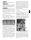
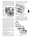
Defrost Speedup Functions — The DFB permits the
servicer to speed--up the defrost cycle. There are two
speed--up sequences: relative speed-- up and an immediate
forced defrost. Speed--up sequences are initiated by
shorting jumper wires JMP17 and JMP18 together (see
Fig. 26); use a straight--edge screwdriver.
Shorting the jumpers for a period of 1 to 3 secs reduces
the defrost timer periods by a factor of 0.1 sec/minute.
(For example, the 90 min run period is reduced to 9 secs.)
The DFB will step the unit through a Heating cycle and a
Defrost cycle using these reduced time periods. This mode
ends after the Defrost cycle.
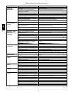
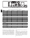
Table 10 – Dip Switch Positio n
Switch No.
12 12 12 12 3
1
1 J 1 J 1 J J 1 On
0 J J 0 J 0 J 0 0 J Off
90 minutes
60 minutes 30 minutes 120 minutes Fan Delay
548J