


59
Internal Wiring
Check al l electrical connections in unit control boxes.
Tighten as required.
Refrigerant Service Ports
Eac h unit system has two
1
/
4
” SAE flare (with check
valve s) service ports: one on the suction line, and one on
the compressor discharge line. Be sure that caps on the
ports are tight.
Compressor Rotation
On 3--phase units with scroll compressors, it is important
to be certain com pressor is rotating in the proper
direction. To dete rmine whether or not compressor is
rotating in the proper direction:
1. Connect service gauges to suction and discharge
pressure fittings.
2. Energize the compressor.
3. The suction pressure should drop and the discharge
pressure should rise, as is normal on any start--up.
If the suction pressure does not drop and the discharge
pressure does not rise to normal levels:
1. Note that t he evaporator fan is probably a lso rotating
in the wrong direction.
2. Turn off power to the unit and install lockout tag.
3. Reverse any two of the unit power leads.
4. Re-- energize to the compressor. Check pressures.
The suc tion and discharge pressure levels should now
move to their normal start-- up levels.
NOTE: When the compressor is rotating in the wrong
direc tion, the unit will make an elevated level of noise
and will not provide cooling.
Cooling
Set space thermostat to OFF position. To start unit, turn on
main power supply. Set system selector switch at COOL
position and fan switch at AUTO. position. Adjust
thermostat to a setting below room temperature.
Compressor starts on closure of conta ctor. (08D–09D:
Second stage of thermostat will energize Circ uit 2
contactor, sta rt Compressor 2.)
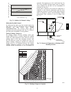
Check unit charge. Re fer to Refrigerant Charge section.
Reset thermostat at a position above room temperature.
Compressor will shut off. Evaporator fan will shut off
afte r a 30--second delay.
To shut off unit -- set system selector swi tch at OFF
position. Resetting thermostat at a position above room
tempera ture shuts unit off temporarily until space
temperature exceeds thermostat setting.
Heating
To start unit, turn on main power supply.
Set system selector switch at HEAT position and set
thermostat at a setting above room temperature. Set fan at
AUTO position.
First stage of thermostat energizes compressor heating
(08D–09D: both compressors will start). Second stage of
thermostat energizes electric heaters (if installed). Check
heating e ffects at air supply grille(s).
If electric heaters do not energize, reset limit switch
(located on supply--fan scroll) by pressing button locate d
between terminals on the switch.
To shut off unit -- set system selector swi tch at OFF
position. Resetting thermostat at a position below room
tempera ture temporarily shuts unit off until space
temperature falls below thermostat setting.
Ventilation (Continuous Fan)
Set fan and system selector switches at ON and OFF
positions, respectively. Supply fan operates continuously
to provide constant air circulation.
START--UP, RTU--MP CONTROL
Field Service Test, explained below, will assist i n proper
start--up. Configuration of unit parameters, scheduli ng
options, and operation are also discussed in this section.
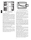
Field Service Test
The Field Service Test function can be used to verify
proper operation of compressors, heating stages, indoor
fan, power exhaust fans, economizer, and
dehumidification. Use of Field Service Test is
recommended at initial system start up and during
troubleshooting.
Field Service Test mode has the following changes from
normal operati on:
S Outdoor air t emperature limits for cooling circuits,
economizer, and heating are ignored.
S Normal compressor time guards and other staging delays
are ignored.
S The status of Alarms (except Fire and Safety chain) is
ignored but all alerts and alarms are still broadcasted on
the network.
Field Service Test can be turned ON/OFF at the unit
display or from the network. Once turned ON, other
entries may be made with the display or through the
network. To turn Field Service Test on, change the value
of Test Mode to ON, to turn Field Service Test off, c hange
the value of Test Mode to OFF.
NOTE: Service Test mode is password protected when
accessing from the display. Depending on the unit model,
factory--installed options, and field--installed accessories,
some of the Field Service Test functions may not apply.
The independent outputs (IndpOutputs) submenu is used
to change output sta tus for the supply fan, economizer,
and Power Exhaust. These inde pendent outputs can
operate simultaneously with other Field Service Test
modes. All out puts return to normal operation when Fie ld
Service Test is turned off.
The Cooling submenu is used to change output status for
the individual compressors a nd the dehumidification relay.
Compressor start s are not staggered. The fans and heating
service test outputs are reset to OFF for the cooling
548J